What is a plane maker’s workshop?
When I first started making planes and was putting together a workshop with a very small budget, I had no idea what form the workshop was going to take – and I still don’t. I started with just a small Tom Senior milling machine, a 5” Raglan screw cutting lathe and a Fobco drill press. Looking back I can see that not only have I come a long way in improving my workshop but also in build and quality of my work. From the start I have always striven to make each plane better than the last. Although I have already covered the subject of my No 982 smoother plane elsewhere on the blog I thought that since I am currently working on the last batch (this plane is limited to 16 of each type, with and without brass cones) I would take the opportunity to described my workshop and some of the machines in it.
Jaespa W220DG Saw

In the beginning I was cutting everything by hand and didn’t even have a wood machine. It was a quantum leap just to get an ordinary band saw. After buying a pull down saw I found it unsuitable as it meant I had to be in attendance full time with the machine to pull down on the handle. I replaced it very rapidly with this Jaespa bow saw. It is the best friend any workshop could have. Very little gets passed this machine.


Here I am taking advantage of the 10 x 10” capacity to reduce the width of a pre-cut bar from my stock for the No 982 bottoms. This machine has a gravity feed controlled by a hydraulic valve which means that in the case of heavy workloads I don’t need to stand with the machine. This allows me to run more than one machine at a time (on occasions several machines).
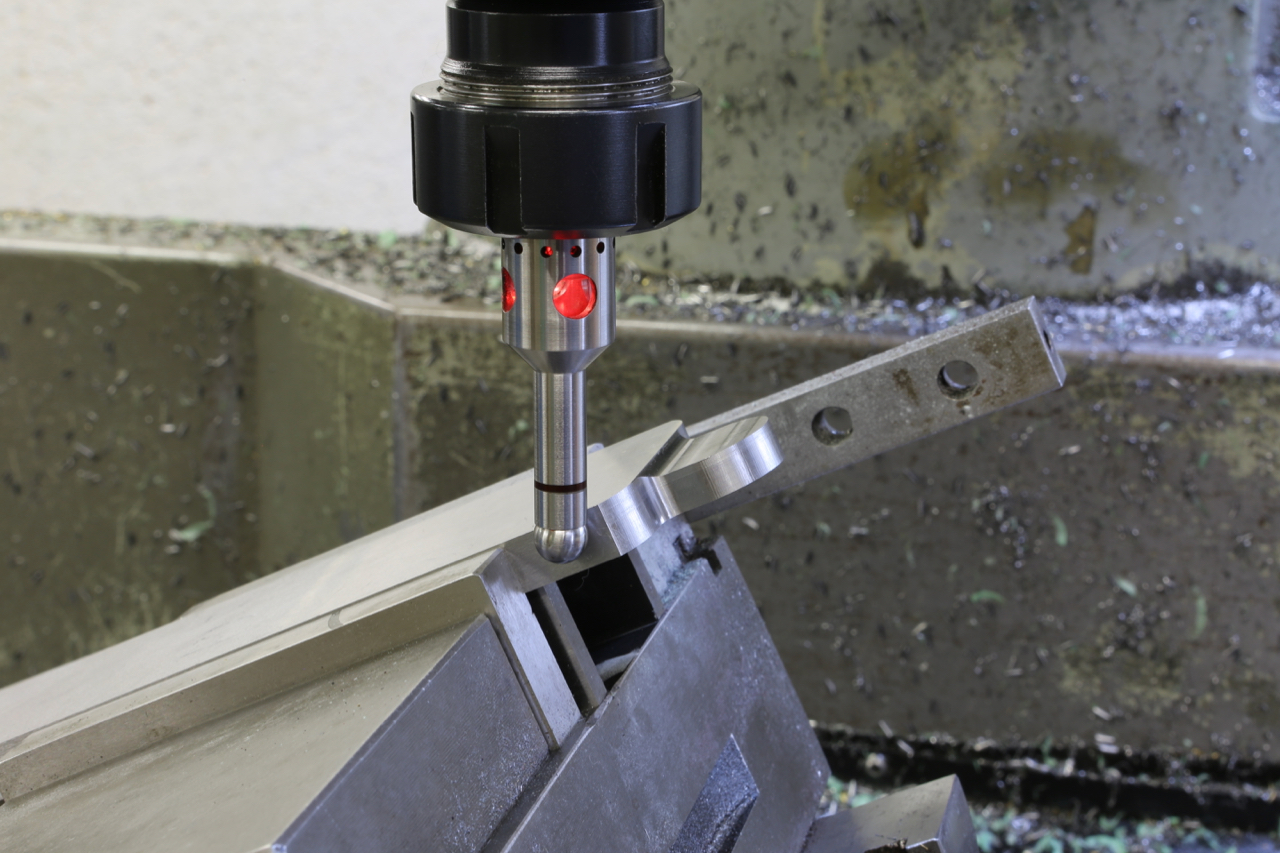
The Milling

In the foreground is my workhorse. A Bridgeport Series II Interact 2, which must be 20 years old and like me, is showing its age. This was one of the early CNC mills controlled by an Heidenhain TNC 151 (by today’s standard it is an abacus). A replacement for this machine would cost a very nice new car.

As you will see throughout all my blogs I use it for many operations and here I am using it to mill and de-scale this hot rolled bar which is to be used for the No 982 bottoms.
This machine is my only experience in programming and it has taken me a long time to reach some proficiency. I wouldn’t want to replace this machine with a VMC but I would like a nice open style bed mill with an Heidenhain control (in my dreams).
Although my current machine performs many tasks it is still limited (in scope but not in work quality) and I sometimes find things easier to do on my manual mill. I have also become very dependent on DROs and no longer trust vernier readings.
It is such a wide range of work that this CNC mill does I no longer want to do my work without it. As much as I might want a CNC lathe I would sooner update my current mill first.
Jones and Shipman 1430 semi automatic surface grinder

Up until 9 years ago I outsourced the grinding for my blades and it was my experience that outsourcing is fraught with problems. I was extremely fortunate to find a machine of this quality which allowed me to do the grinding myself and enabling me to keep everything in house. The machine was originally made in the 1960’s but had just been rebuilt by Andmar (who work very closely with Jones and Shipman to achieve the good build quality). This machine has a good 2’ x 1’ chuck and it has proved very useful for much more than just blades. I have also become very dependent on it for tool making, as I make all my own tools and work holding jigs. In short, this machine has improved the standard of accuracy to everything that is made in my workshop.


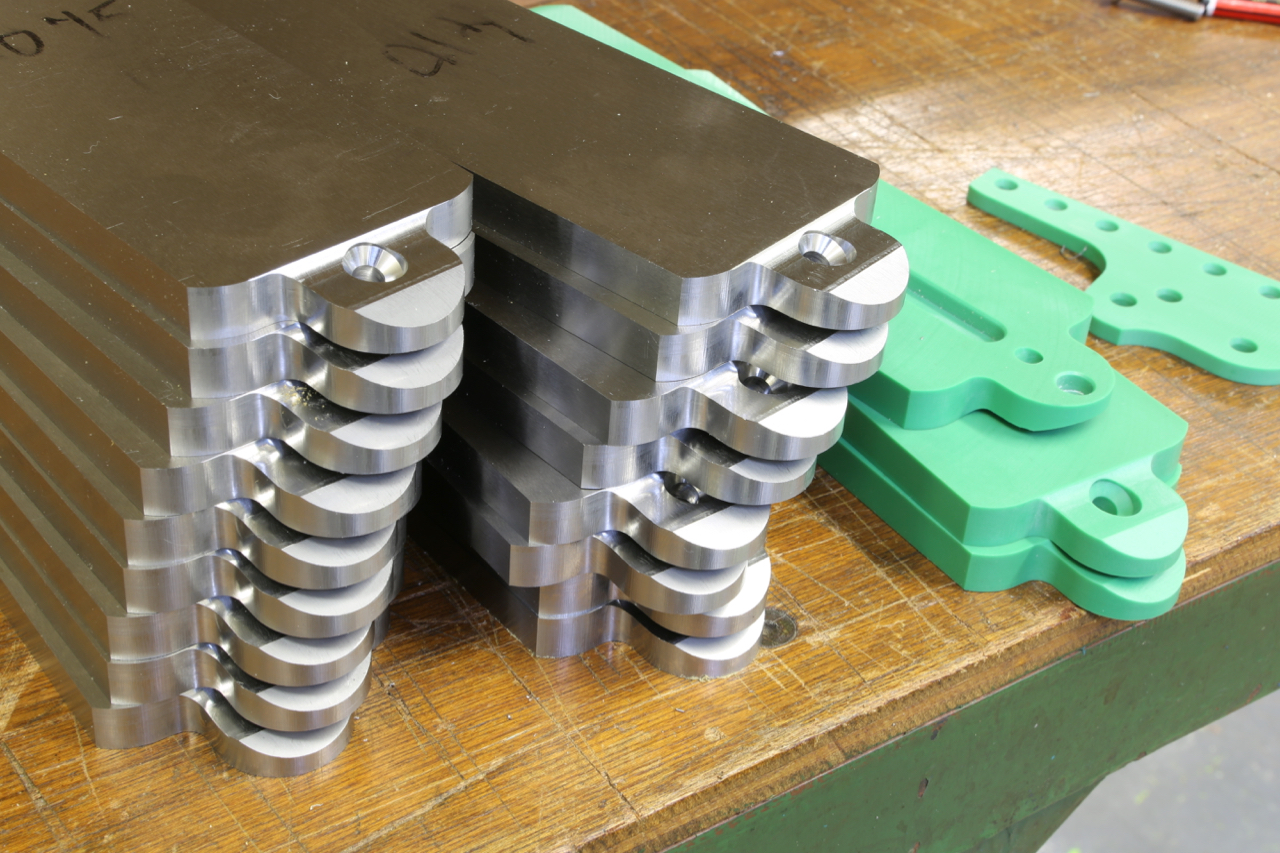
All the bottoms and sides of my No 98 series planes are ground on all sides and again after assembly for the final finish.