These are some renders of my A1 panel plane that Adam Willis has created for me
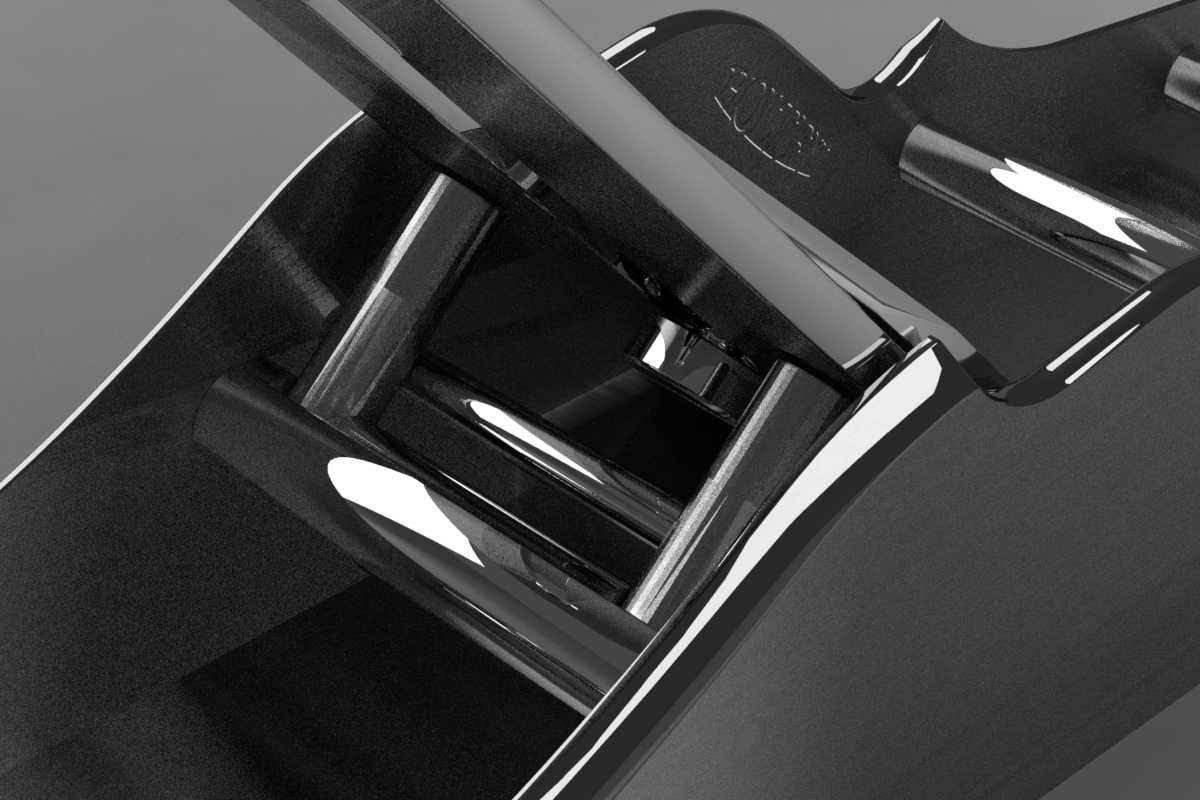
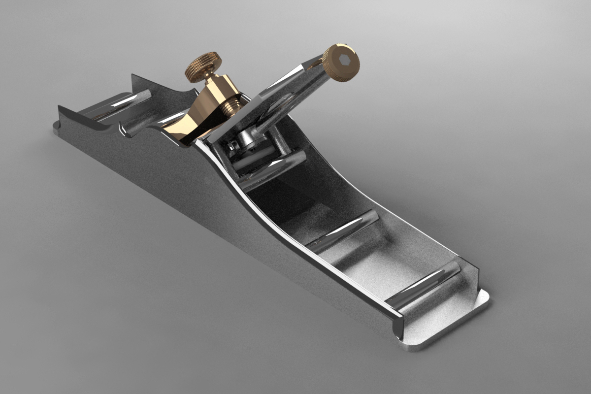
These are some renders of my A1 panel plane that Adam Willis has created for me
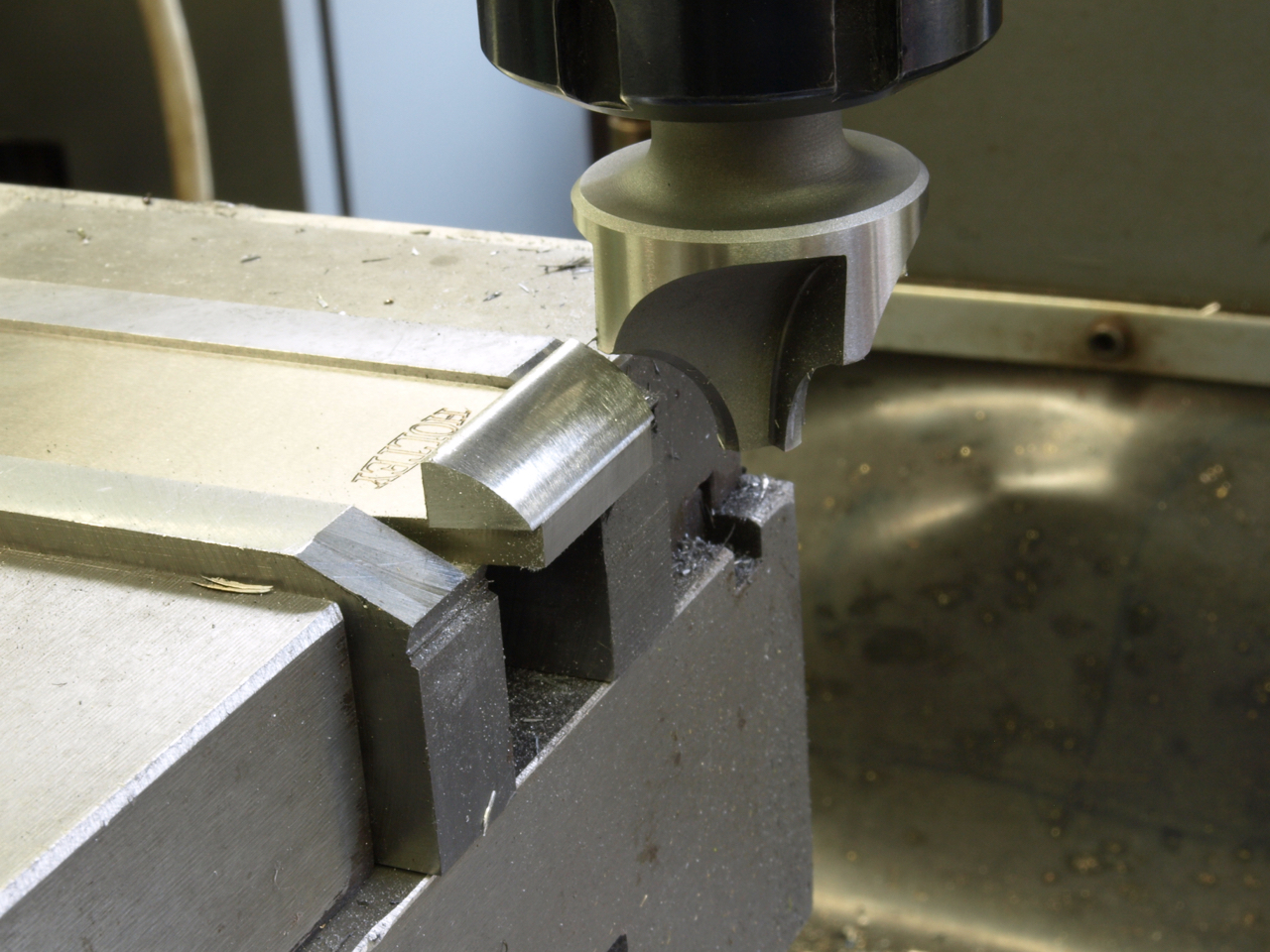
No 10 small finishing plane. The relationship between the sneck piece and the blade.
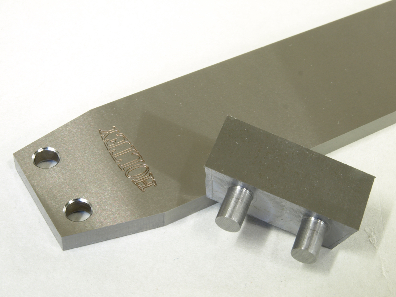
The blade is rejigged so that the milling cutter can follow the original contours of the facet.
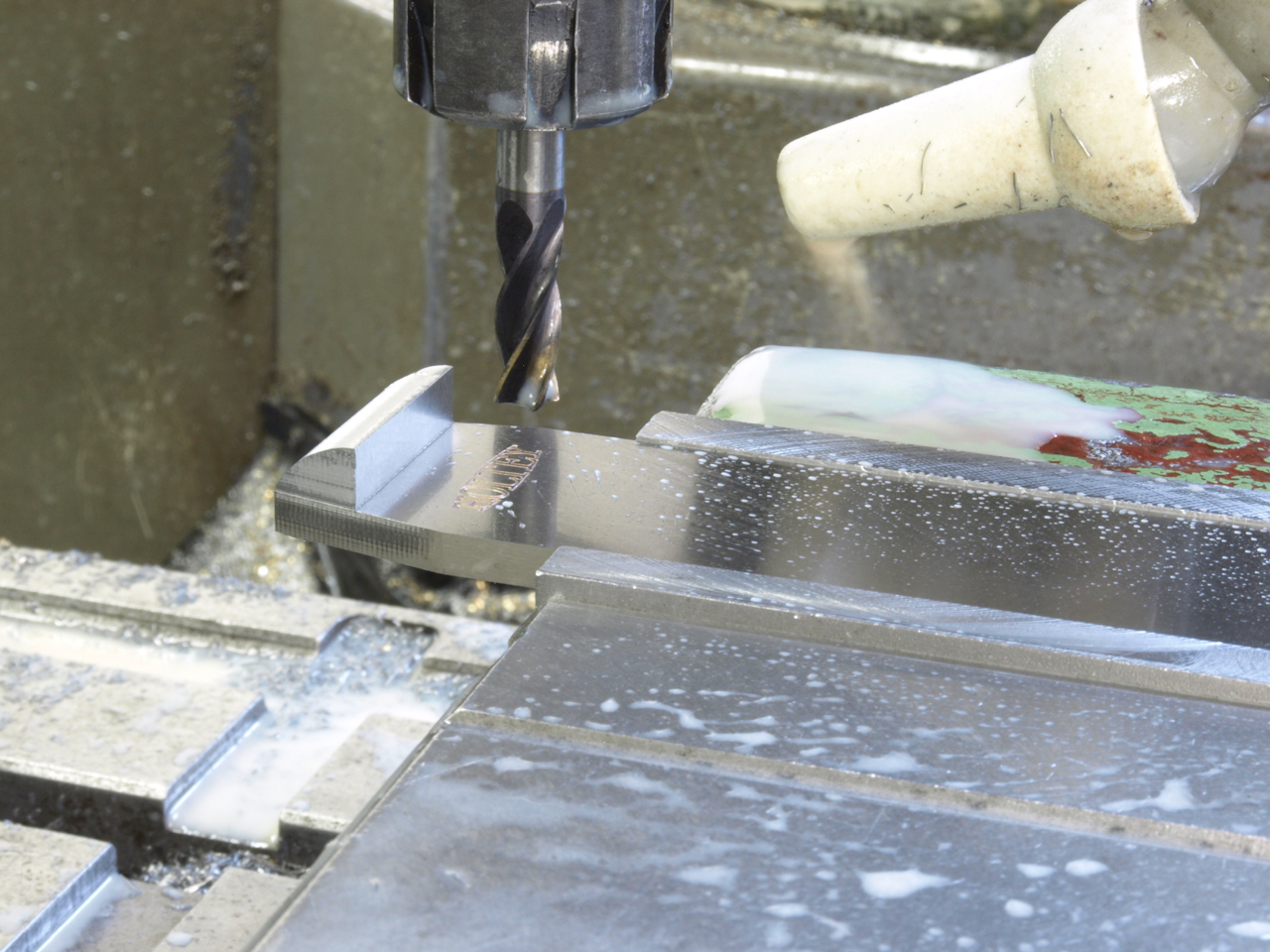
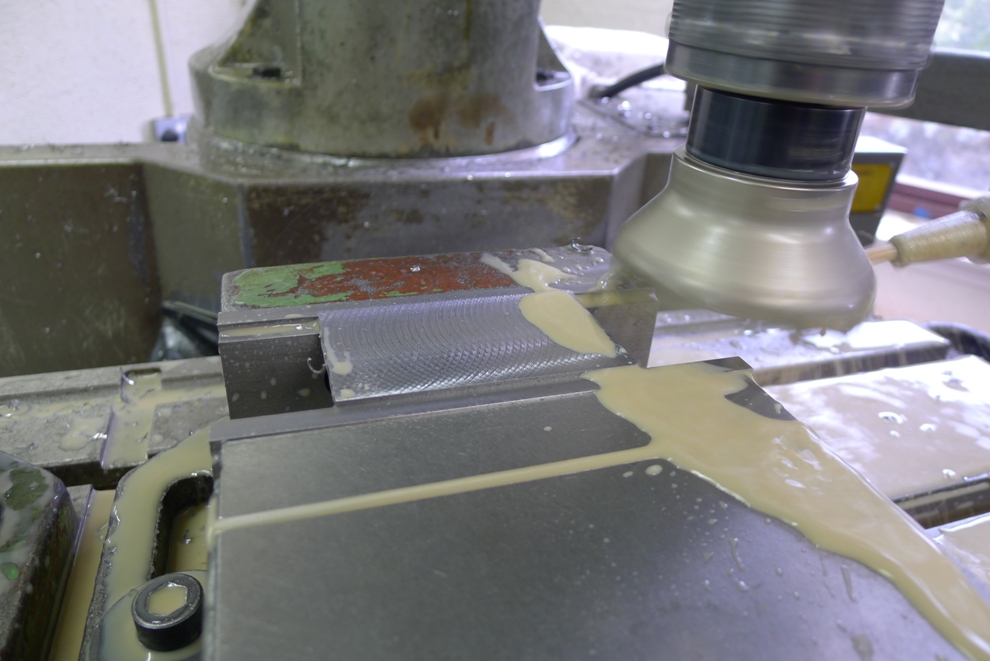
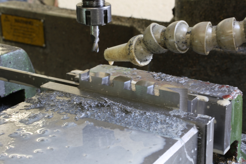
The sneck form is milled after the integral rivets have been peined with a fly press. The blade used at this stage has been hardened and surface ground. The hardening is the only item which is outsourced to a heat treatment specialist.
The finished No 10 blade
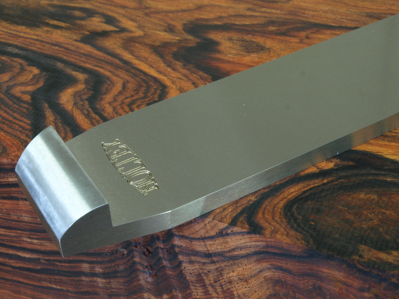
Edge polishing to the sides is usually done with all the sides in a block to keep all the edges true and square.
All my hand work it has to be as good as the machine work, at the risk of looking clinical with no soul ![]()
The pictures don’t do justice to the time spent on every little operation. Although I have taken many photographs along the way I don’t have time to document every little stage. The effort for every detail can seem a bit over the top, and I make little revisions all the time – the overall design will still be as the posted line drawing.
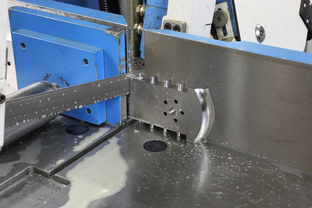
This is a nail biting moment, once I start cutting there is no going back. I can take hours double checking before I separate the toe from the the rest of the sole.
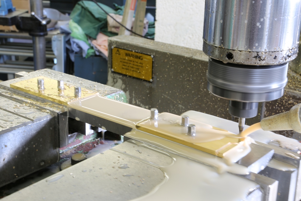
Here I am milling the blade bed. The rest of this operation hasn’t been photographed as I covered this in the No 983 blog and it is almost identical as are the adjuster recesses. You can see that the work holding vice jaws are purpose made just for this plane. This enables me to get a firm grip.
All my buns start off as a true square block. All drilling, tapping and recessing is carried out on the mill
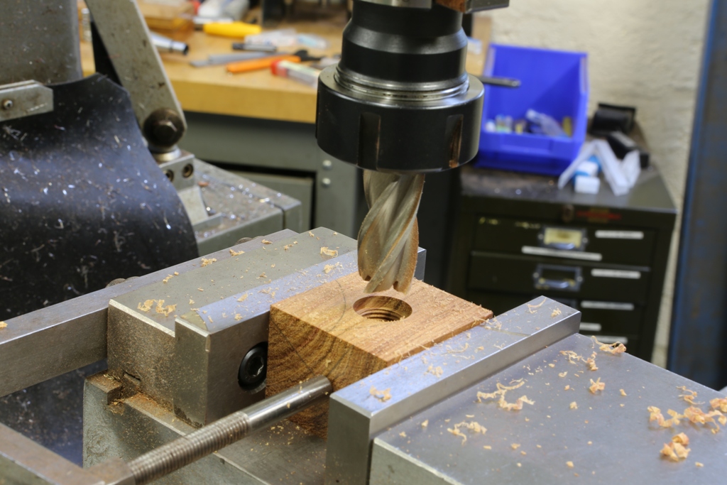
The bush shown here is to be epoxied into the front bun. You can use some imagination as to how I arrived here. The combined strength of the bush and its bun is considerable. Note there are two flats which make it impossible to remove the bush once the epoxy has cured.
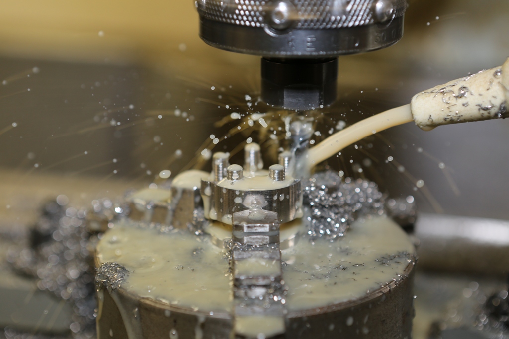
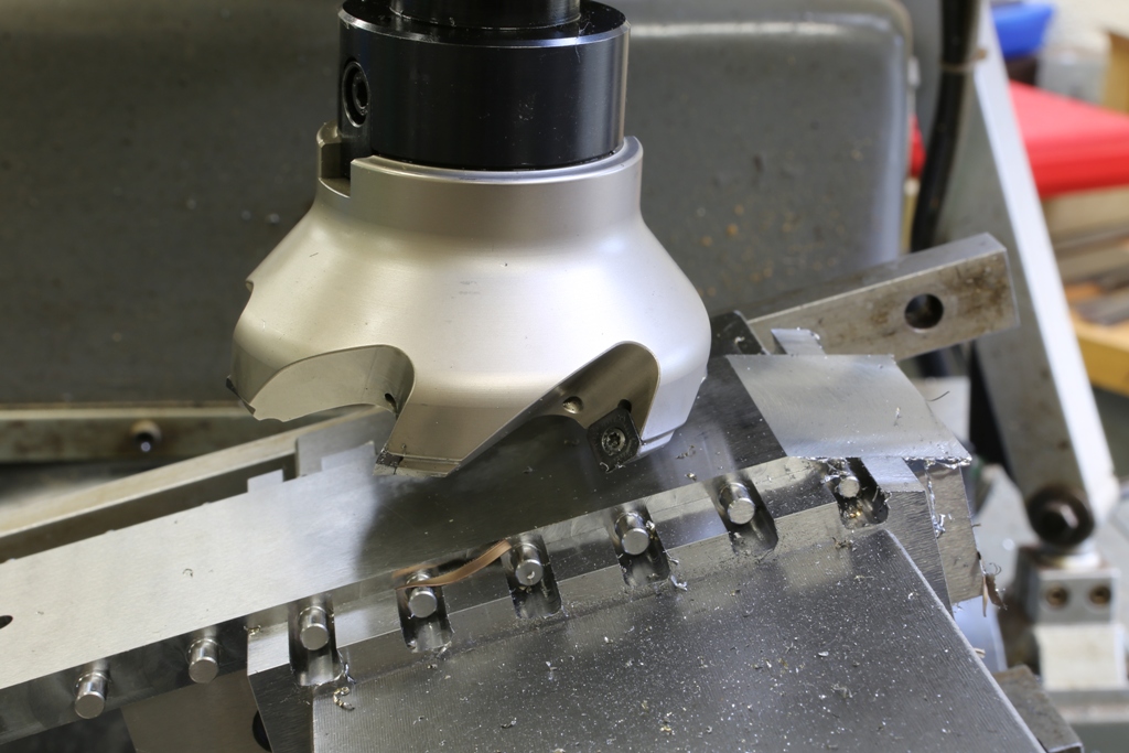
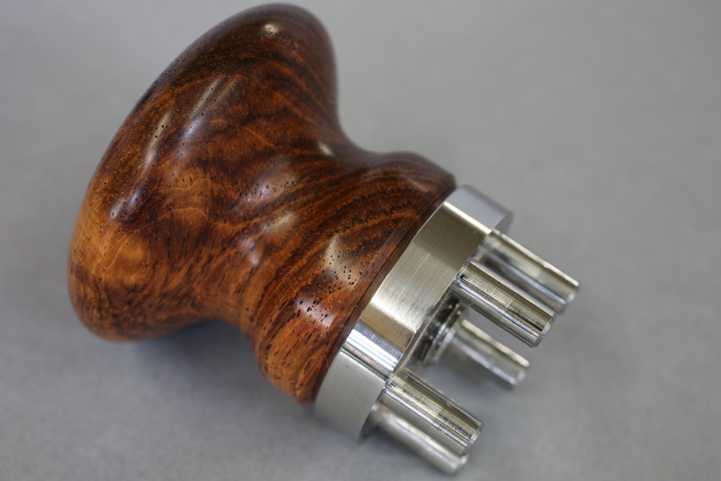
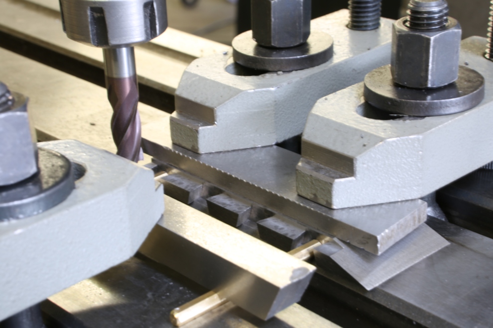
This is the milling operation for the five integral pins/rivets to the bun boss.
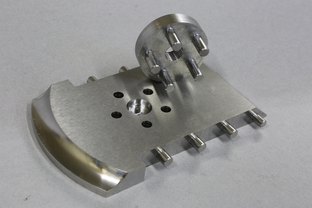
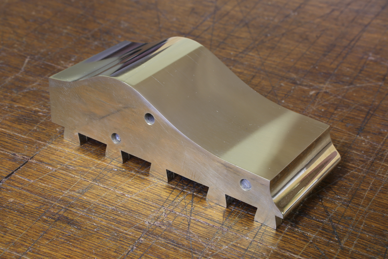
This is the finished boss for the front bun. I have chosen this method of fixing for its strength. I wasn’t happy about tapping blind holes. Who cares, it is not about cost ![]() It is going to be the only one of its kind.
It is going to be the only one of its kind.
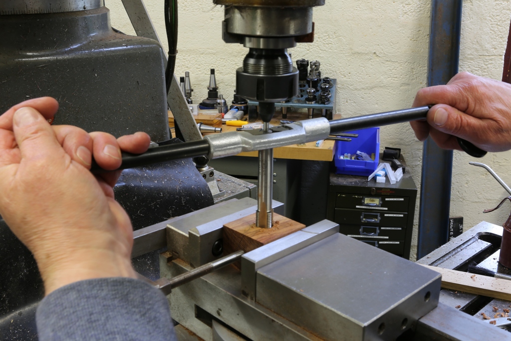
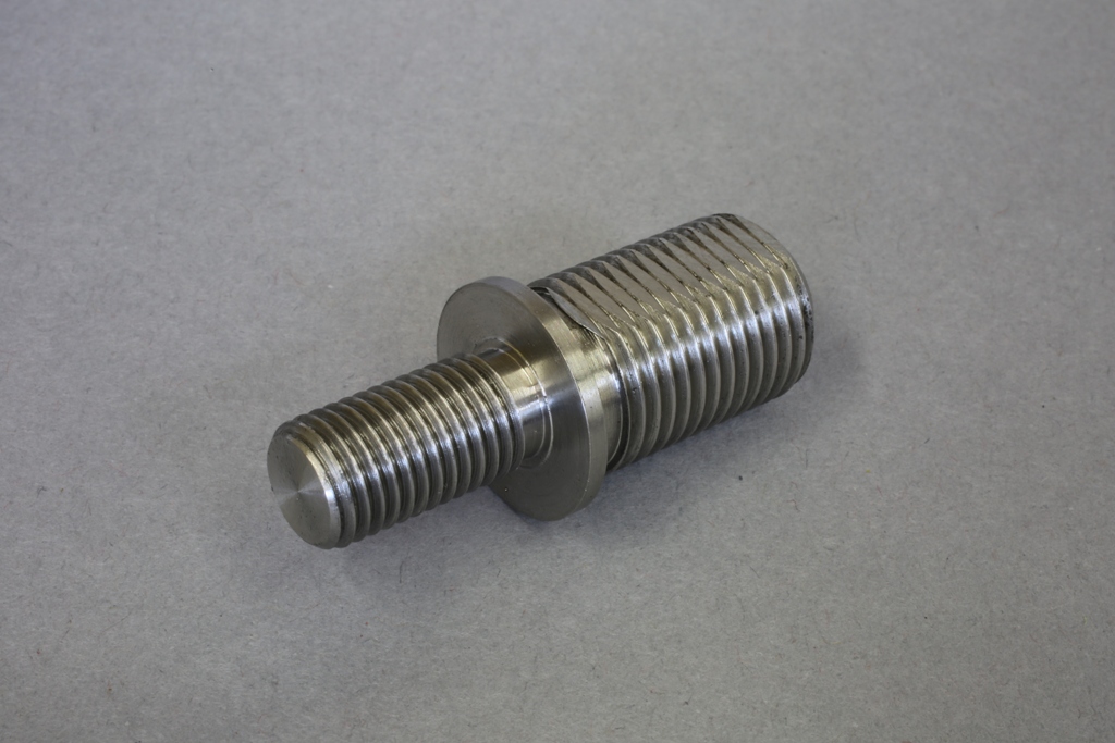
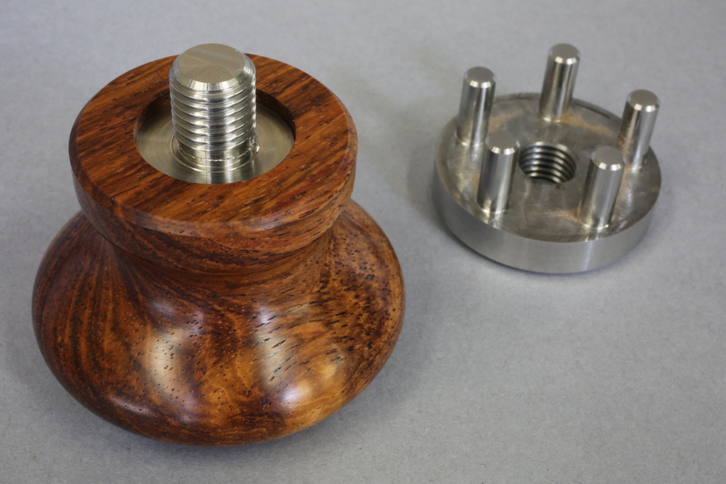
Illustrating the fitting of the bush to the bun and the threaded nose to fit the finished bun to its boss.
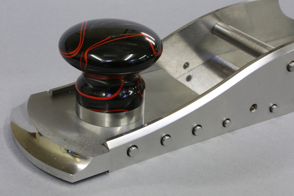
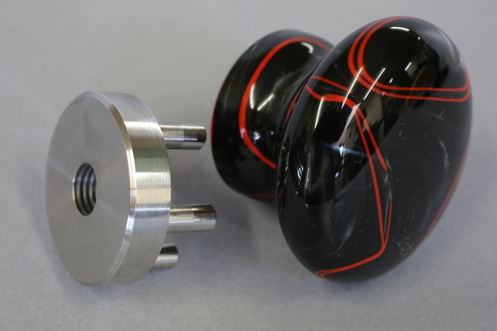
Once this is complete, the bun can be removed and the boss is ready to rivet in place. Note that I used a V joint between the boss and the knob base. The knobs will leave my workshop perfect but the rotary position of the knob can have a tendency to migrate and wood can lose its concentricity over time. Also when the knob is removed and refitted the sharp edges can be bumped, thus losing the desired effect. The V joint will hide any of these unsightly dinks.
Temporarily assembled plane.
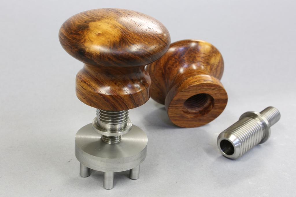
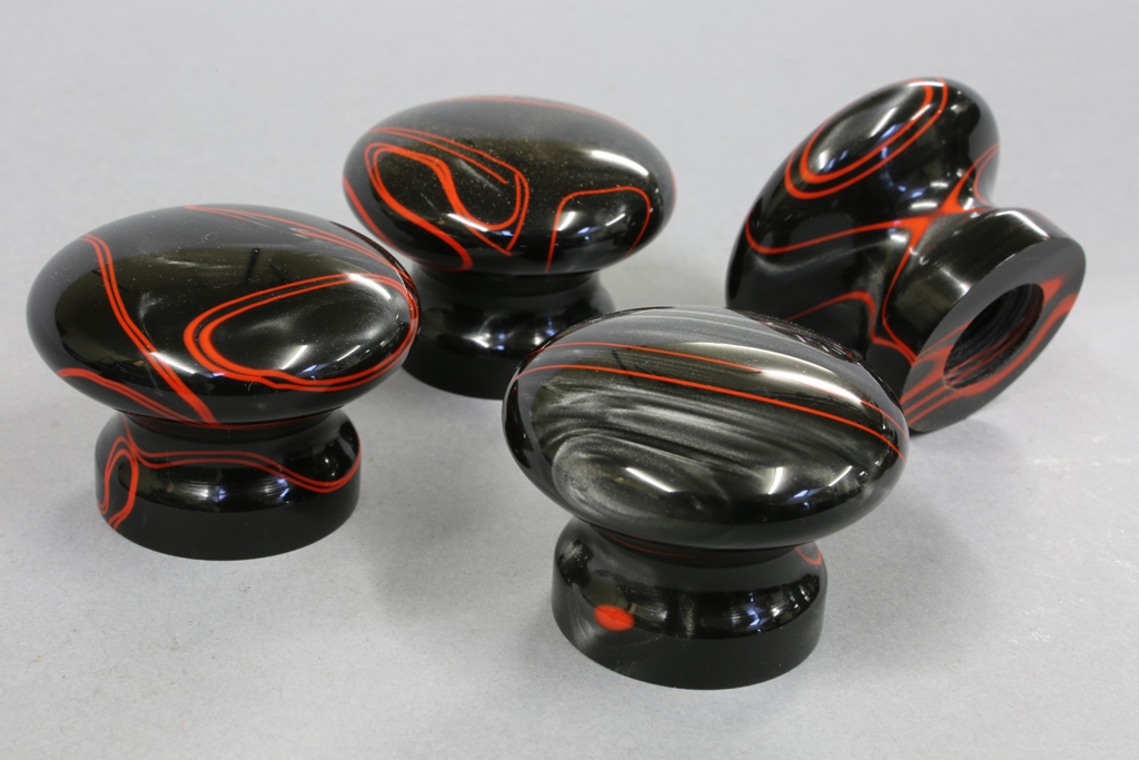
A general selection of knobs and parts.
Still a long way to go, sorry to those who have a plane on order.
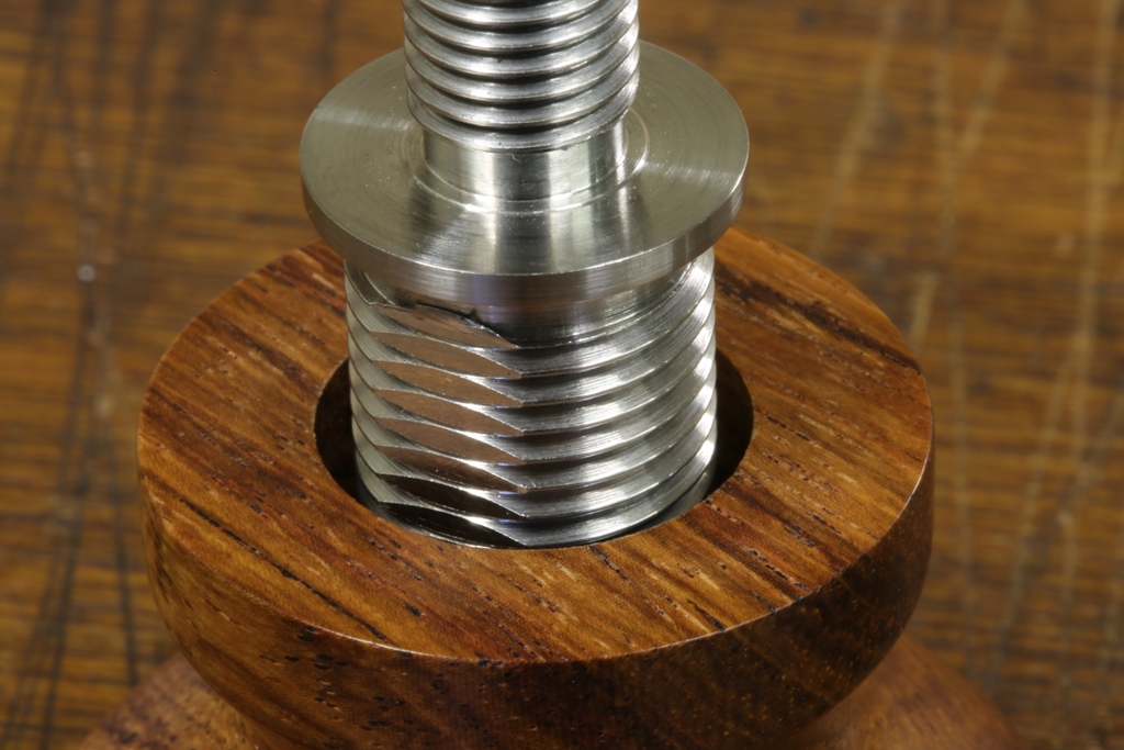
Thought this was worth a picture and mention. The bushing here had been cemented with epoxy and I had started it with a few threads and then I was distracted ………
I discovered how strong this system is when I came back the next day. I will keep this as a reminder.
Chariot Plane
I find that I try to avoid using the term A28 because there is a lot more here than on the original A28 plane. These six are the last I will make as the cost of making is too high.
One of the original A28 Norris planes was sold at David Stanley’s auction Sept 2014 for £8,000 (+ commissions). In the light of this my price of £4,800 is very reasonable, especially as my plane is far superior in quality and construction. Who knows what these will be worth when I am gone.
There are some who would think that because this is cut out with a CNC mill there is no work here, to them I say “make one” ![]() There was a lot of work to get here and still a long way to go. (all finished now – look out for the next project).
There was a lot of work to get here and still a long way to go. (all finished now – look out for the next project).
Progress on my A28 Chariot Plane
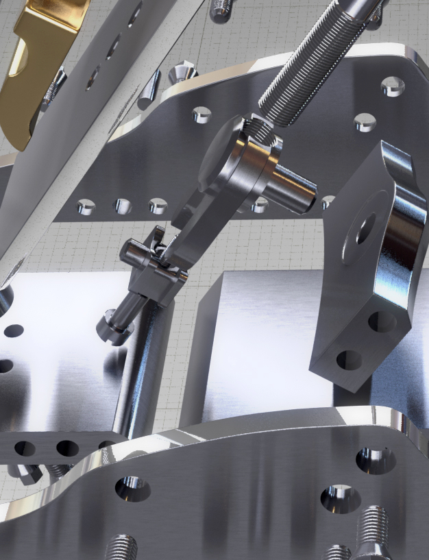
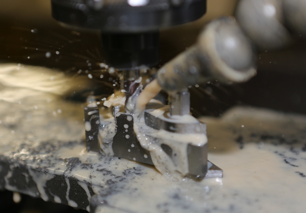
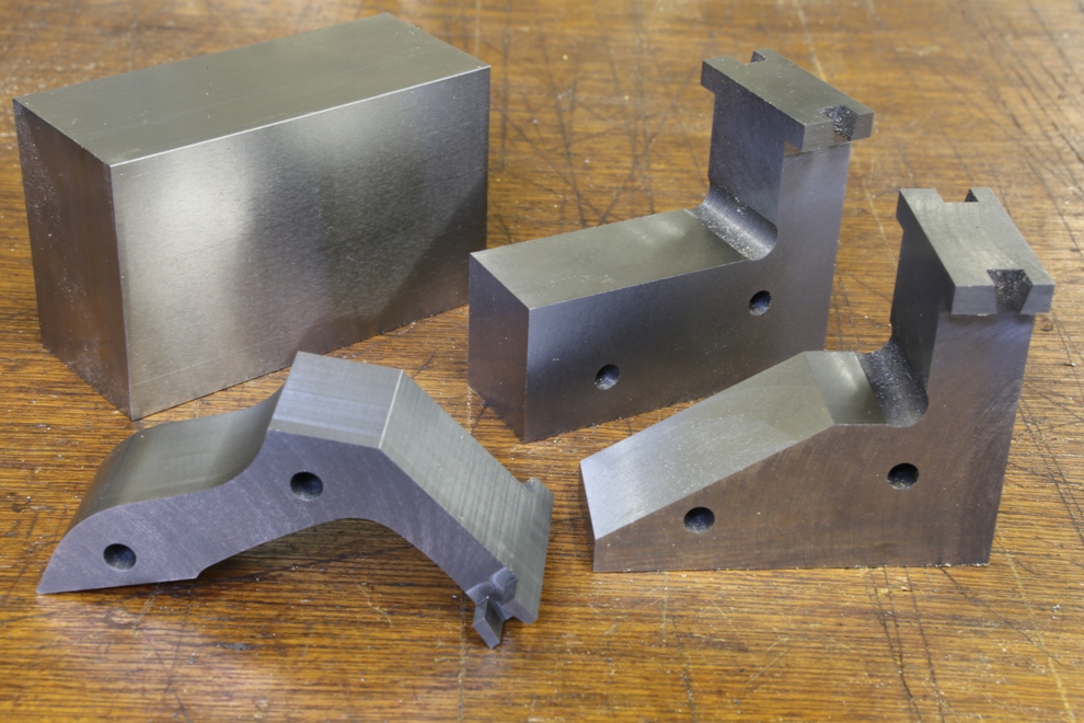
This picture shows some idea of all the work that goes into this plane. Unless you have done it yourself you can never imagine the effort and thought that goes into making this Chariot. This plane is made to a standard light years beyond its original counterpart made by Norris.
During the working of this A28 plane I have been neglecting this blog but now I am ready to update which I will do over the next few weeks.
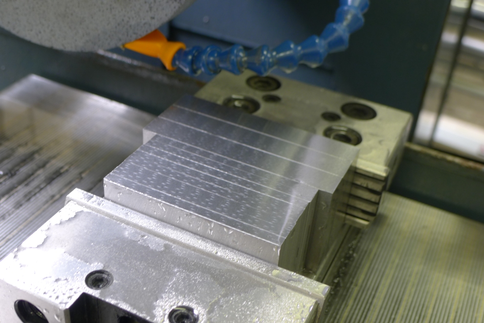
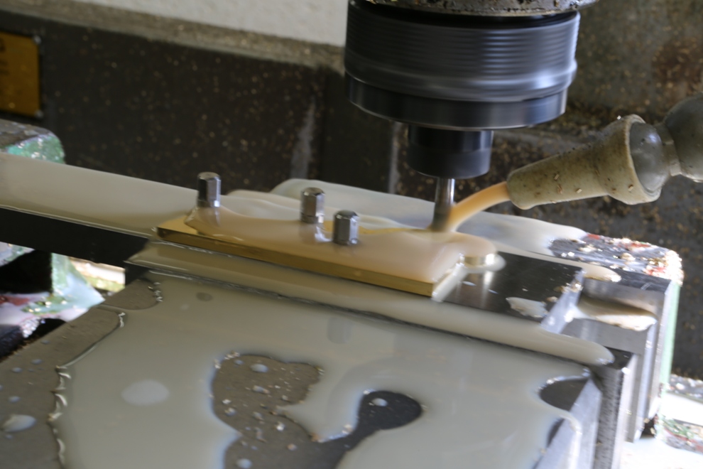
All the sections I use are cut out of stock material and brought down to size, by sawing and milling.
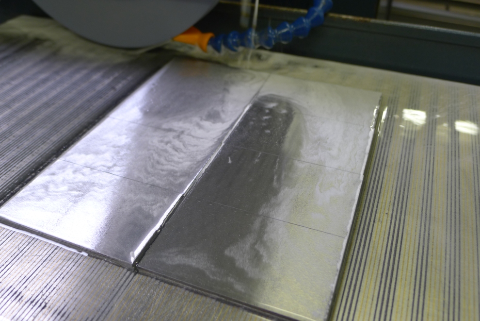
As most of my working and setting out depends on a high degree of precision (which has never existed before) surface grinding in the early stages allows me to achieve my goals.
This picture shows the edges being ground. This is also important to have a true pinch dimension. I need this for the dovetailing.
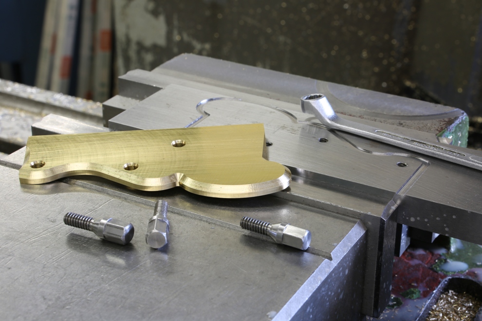
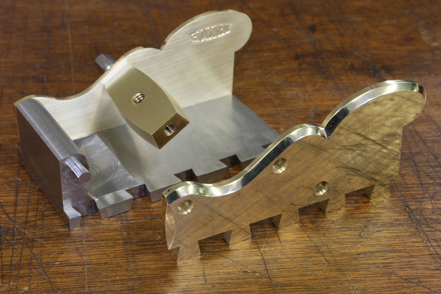
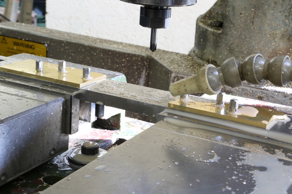
Jigs and work holding fixtures are also all made to precision. After much preparation work to the brass, similar to the steel work as described. Then rivet positions are drilled and I am able to screw these sides with purpose made bolts to the fixture for profiling and chamfering.
After routing out the profile then the chamfering is completed whilst the sides are still jigged.
Just overall set up pictures.
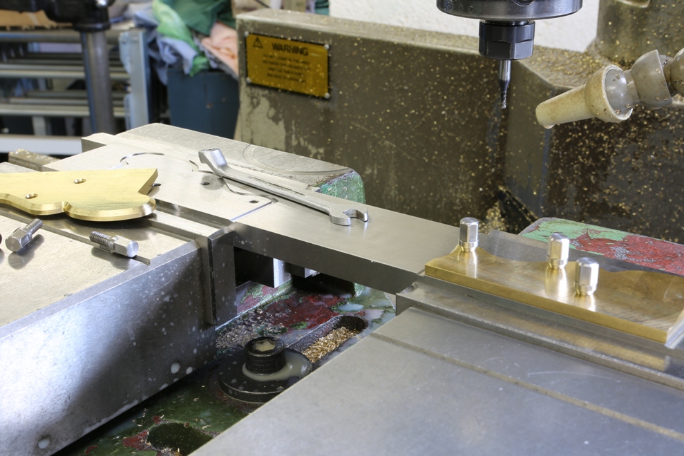
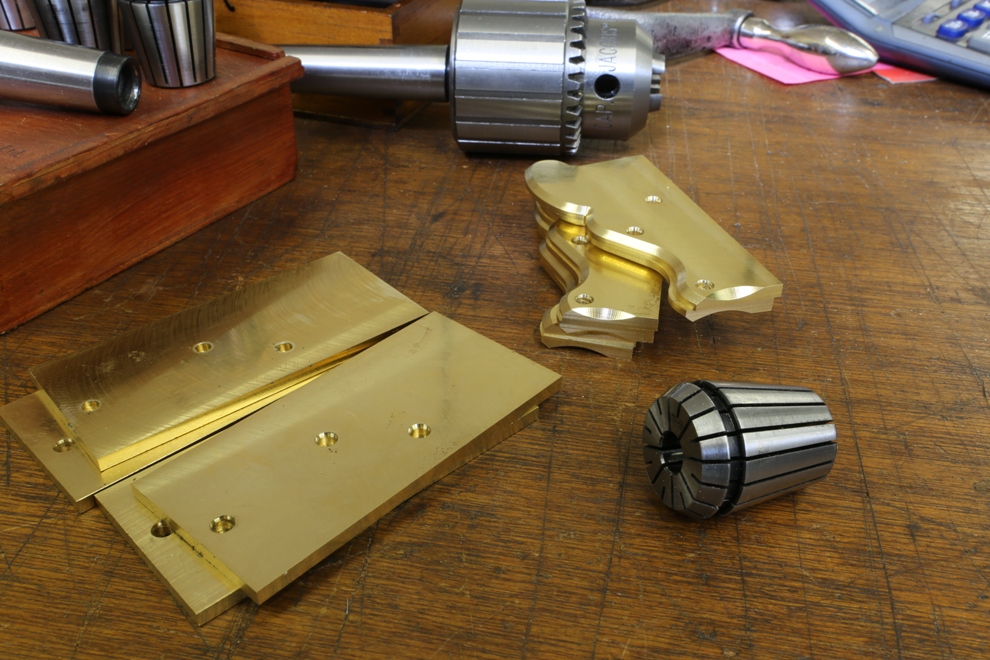
Here are the some sides already milled and some pre-prepared waiting for profiling.
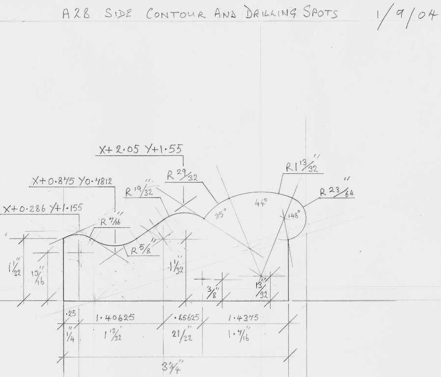
This Chariot is the last item in the series of low angle planes I have been making recently. I have only made a few of these planes and that was a long time ago in my early days of plane making. Then my side profiles were cut by hand and I made up a template which I would scribe round. Now that I CNC these the machine can’t see my template so I have had to re-draw it showing co-ordinates to write a programme from.
This line drawing by today’s standards might look a bit primitive but I have never had the leisure to learn to use a CAD. With a drawing showing contours I can write this in to my control unit. Drawing contours is more instinct than anything and I just know when it is right however long it takes (I would be ashamed to tell you how long these ones took).
Back working on the Bullnose after so much downtime with the grinding machine maintenance:
Pictures 1 – 4
This is the cast iron infill for the Bullnose. As you can see this is a complex shape so I will let the pictures speak for themselves. As with most things I design and make I go places that have never been visited, making these planes very unique.
This shows the pin side of the dovetails being milled.
Rebating the tops of the dovetail area, which provides a light stop and gives the dovetails a better form. Again this system is unique to my planes.
Powered by WordPress
Dovetailing v peining v screwing v in situ doweling
Lets start with dovetailing. The effectiveness of a dovetail must be compounded so that you show a dovetail form on two sides. That means you are going to have a void on one side which will need filling. You will need a bit of extra material left on the ends of the pins and dovetails. This means you have to move the metal around by peining to fill the voids. You have already picked up on my pinch formers and the clamping plates which are made to fit inside the dovetails. All that peining is going to push a lot of things around. Another problem is that there is going to be pressure along the line of dovetails which will then convex the sole. If it doesn’t then you are not peining it hard enough, you want to stuff as much material as possible into those voids. There are good and bad dovetails around. Once everything is all snug and finished there will be a lot of material to flush away and the bottom needs to be flattened on the mill. Also the sides need to be treated in a similar way. I don’t know how far other people go with their dovetailing but this is how I do it. You will notice how true each tail is. All lines are straight and sharp. The former is kept parallel and is the same width as the pinch sides of the bottom. In my language this is a F******g load of work.
There are two other options. One of these is to form dowels in situ on the bottom which has to be a very accurate process to match with the corresponding holes on the sides. This process needs to be done on a CNC. All in all the work is probably equal to the dovetailing as the peining is a very boring process and has the same effect of causing a lot of pressure with the same problems as above. i.e. you are putting in a lot of stress.
Screwing – is probably a little more work as I am not going to buy a box of screws out of a DIY shop – they are purpose made by me. They have a counter sink angle of 40 deg unlike the 90 deg on a standard screw. Also the screw requires a plain shank as a positioning reference. The heads of the screws need to have a positive drive as they are going to be to a required torque. The angle of the countersink has to be tighter at the top than at the bottom. So as they tighten there will be some metal displacement so there will be no gaps or joints showing. Each screw is then thread locked. With this stage complete the heads can be cut off and the body is then milled true. There is more work in making each screw than one dovetail. But this process has a plus factor by not loading the chassis up with stress.