These are some renders of my A1 panel plane that Adam Willis has created for me
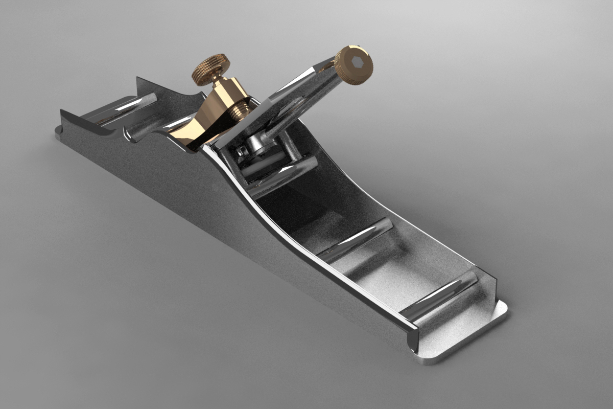
These are some renders of my A1 panel plane that Adam Willis has created for me
I couldn’t find this picture earlier on, but it has now appeared
This is one of the best adjuster I have ever made, and I hope to revisit this but it is only suitable for a bevel down plane
I still keep revisiting the drawing board making final adjustments to my new plane the No 985 – seems to go on forever. Whilst I have been doing this I have been making comparisons between non-adjuster planes and adjuster planes and I am working on the basis that having an adjuster does double the price. I will try to explain the difference and why the work compounds.
Since designing my own planes I have moved on a long way from the earlier Norris examples. The Norris planes with their adjusters did tend to be a bit basic, like most planes of this time, almost bordering on primitive. You could literally recess the infill and drop the adjuster straight in, securing with two wood screws.
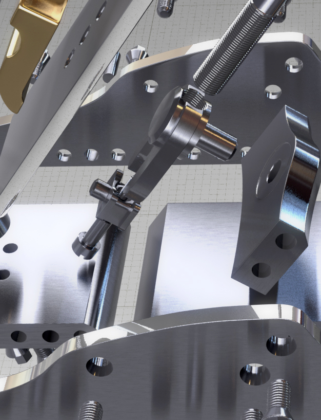
I will explain with an example of where a lot of the work goes, which doesn’t appear to have much to do with the actual adjuster. My adjuster designs are truly integrated into the plane, I don’t just pop an adjuster in as an extra!
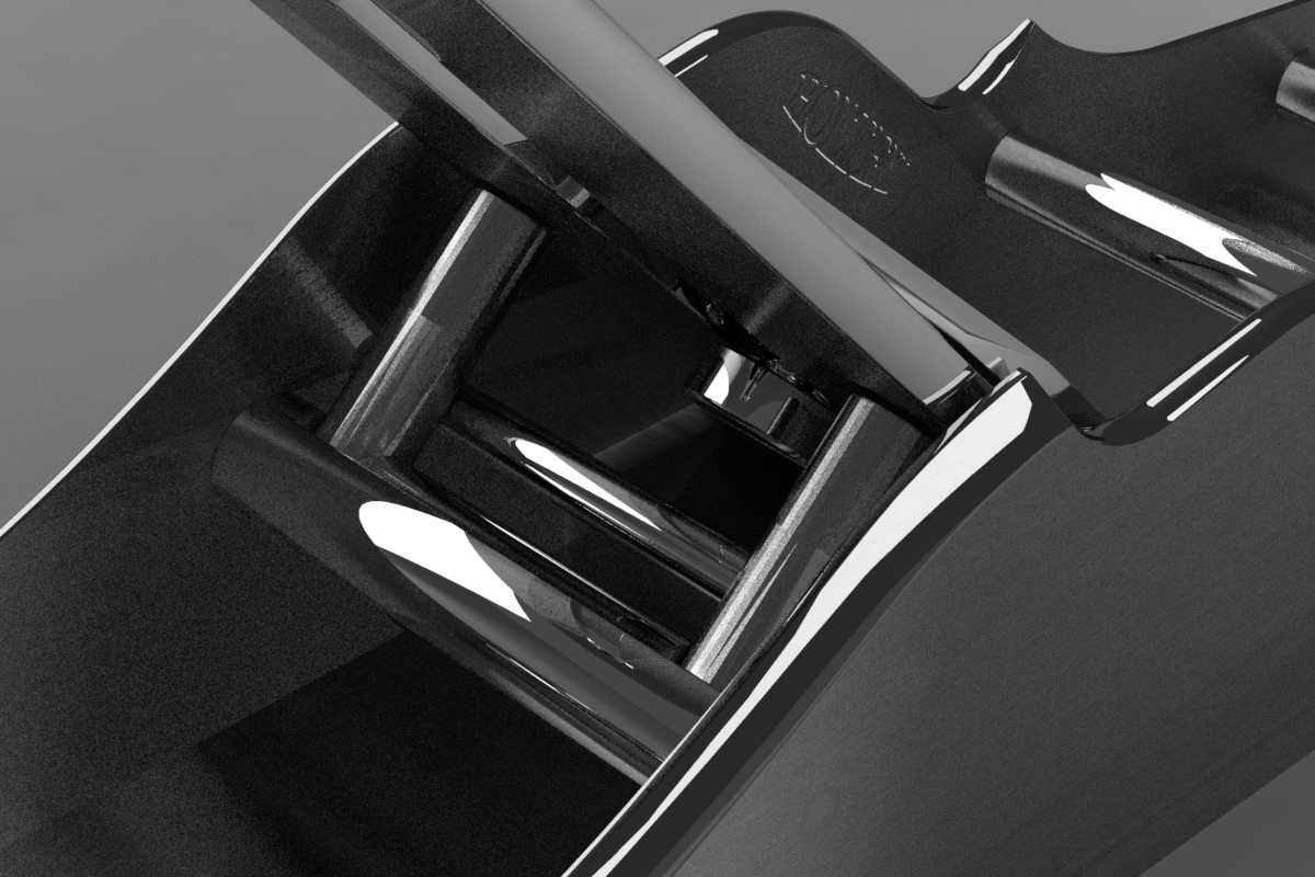
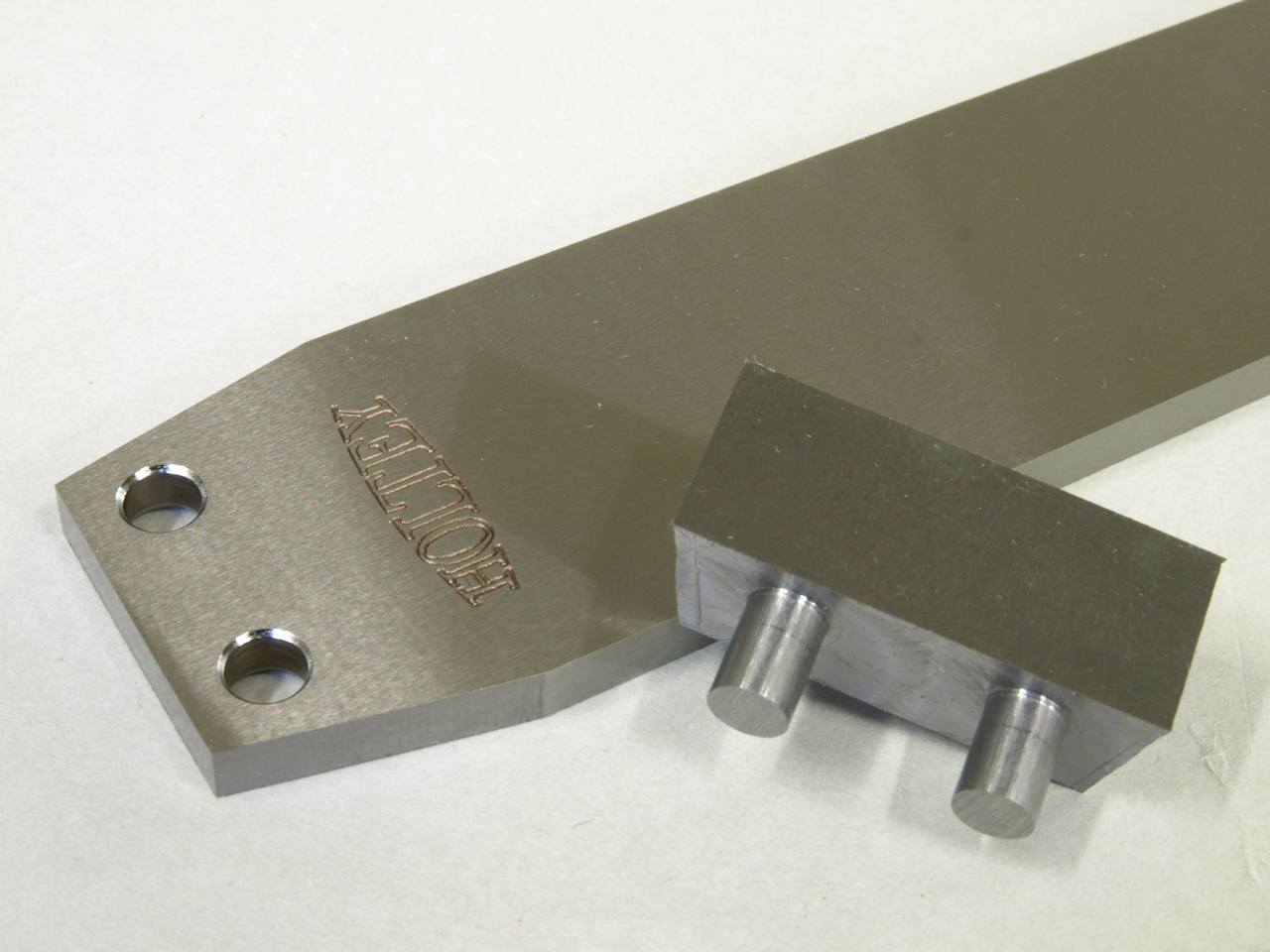
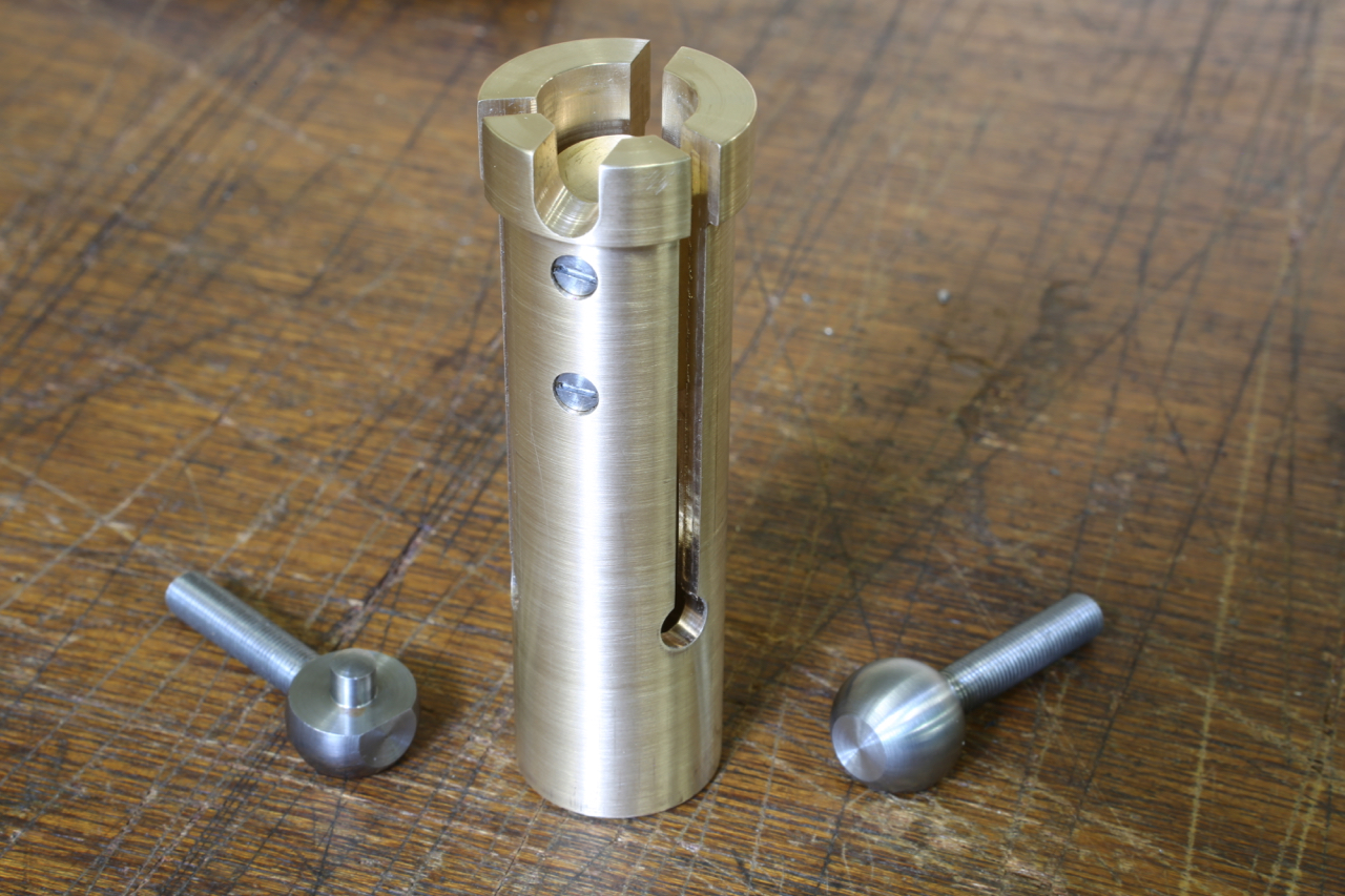
The photo below shows the swivel which is balled so it matches any irregularities whilst connecting with the blade. This is, like most of my design elements, my own innovation.
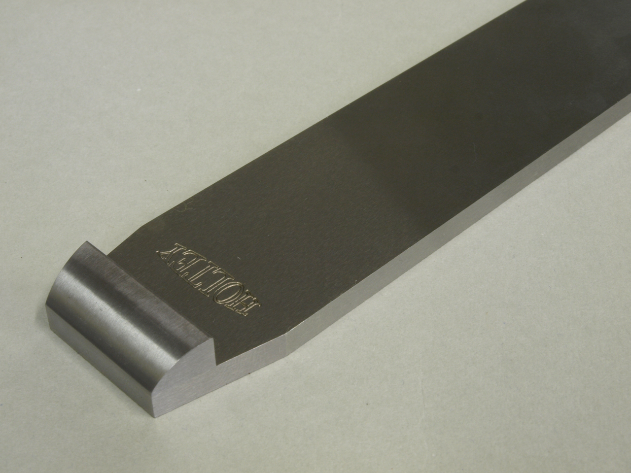
As you can see the lever cap (from my No 984 plane which is blogged here:http://www.holteyplanes.com/blog/category/no-984/, showing the machine working) is stepped/recessed so that it will carry a swivel. This is necessary with adjuster planes as the swivel shoe will bridge the adjuster holes in the blade. From my research it appears that I am probably the first pioneer to drop the chip breaker on bevel down planes. The first plane I made like this was the 11-s (see photo)
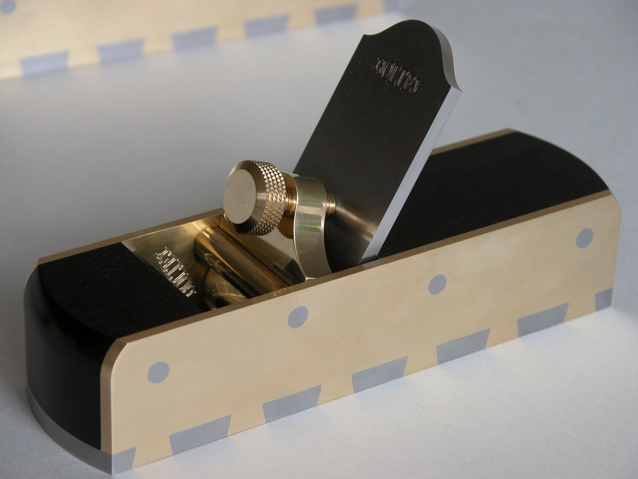
As the 11s has no adjuster drillings the lever cap was quite straight forward and less work. When I made the No 982 I was able to avoid the holes in the blade with the lever cap placement but it put some limitations on the design.
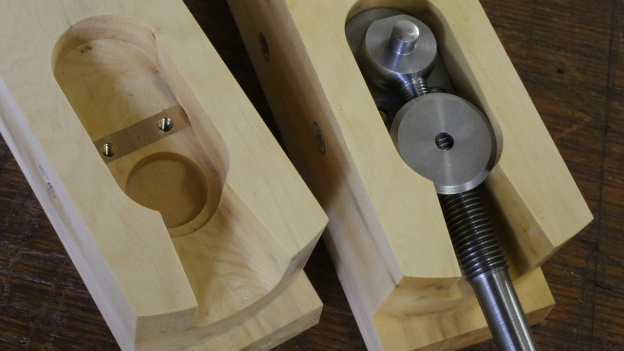
This is an example of the adjuster recessing in the No 983.
This is the bottom for the No 984 showing the adjuster recess.
In summary: to add an adjuster, both adjuster and plane have to be truly integrated. Of course the adjuster has to be made as well.
I am hoping to get some feedback here, so please register if you haven’t already and comments will be appreciated.
Snecked Blades
In the course of my research I have found that the only planes that were made with snecked irons were shoulder planes, and the occasional thumb and chariot planes – these were side snecked as in my 11-s smoothing plane here (double sided sneck).
Mitre planes usually have top snecked irons, as in my No 10 shown here.
I can’t understand why smoothers and panel planes etc did not have snecked irons. Of course top snecking would require a longer blade as lever cap or wedge would restrict their use. A side sneck should still work on these planes.
Is it possible that the use of chip breakers had something to do with this?
I am working on a development plane at the moment and planning to make it a non-adjuster plane. I feel that having a snecked iron will make a considerable difference in setting up the blade. I am also wondering if users choose to use a non-adjuster plane because it is better or is it an elitist thing?
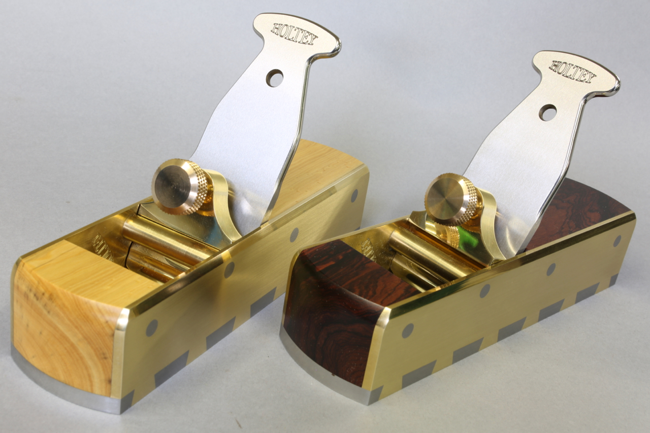
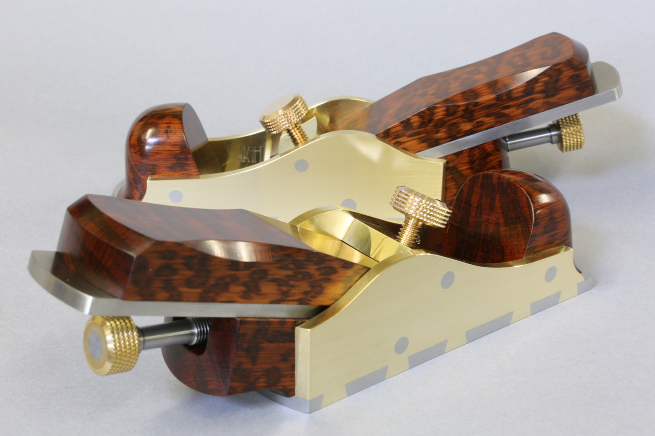
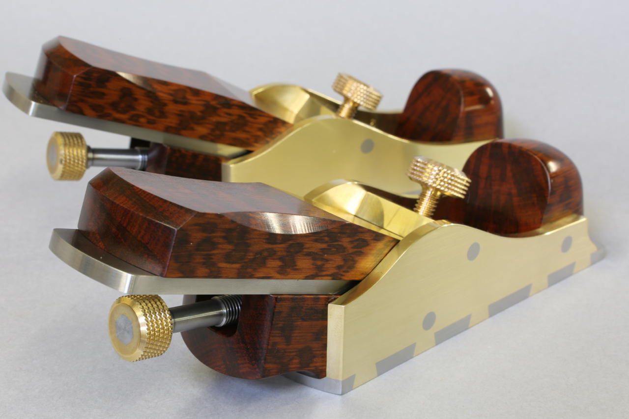
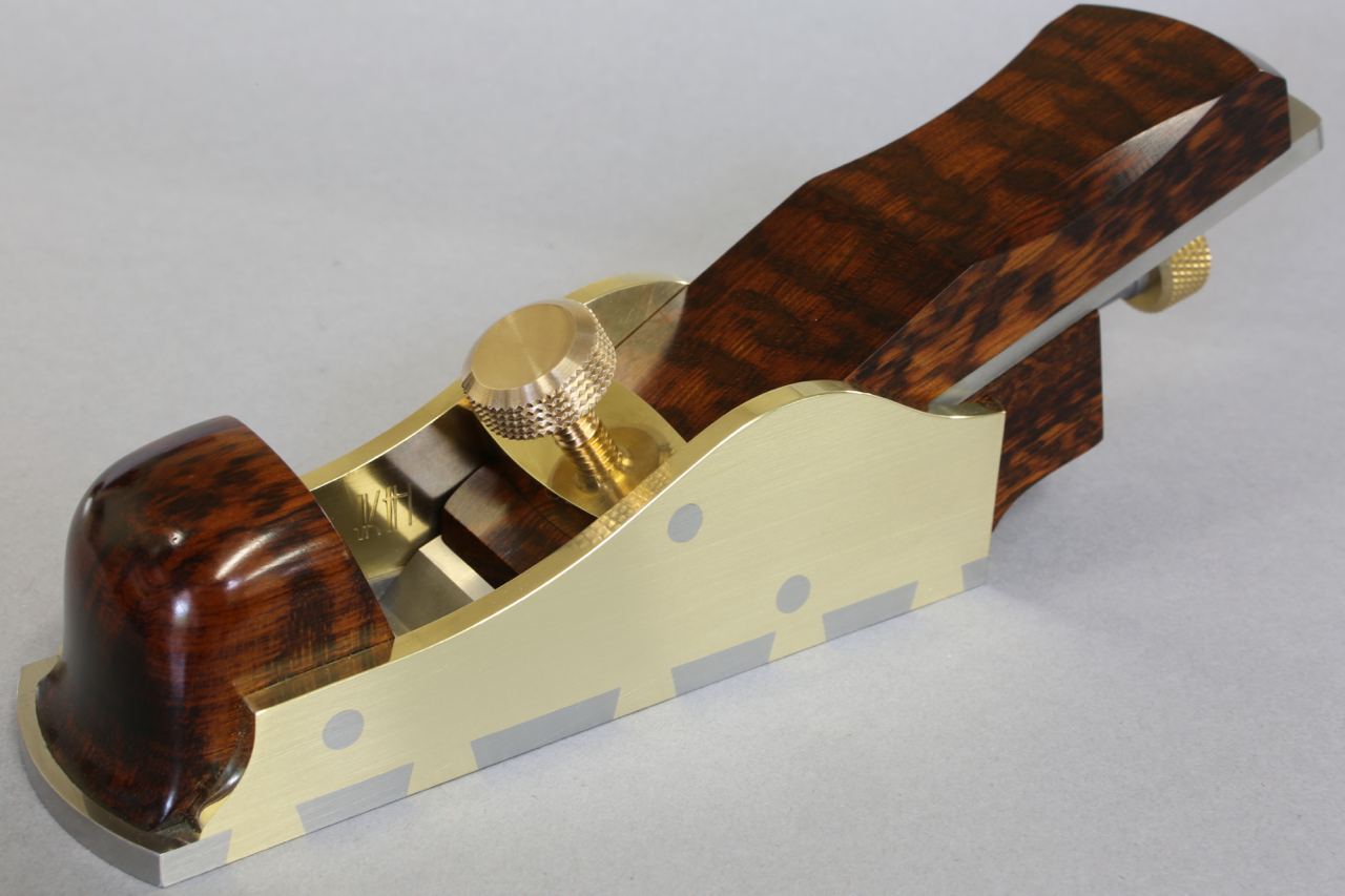
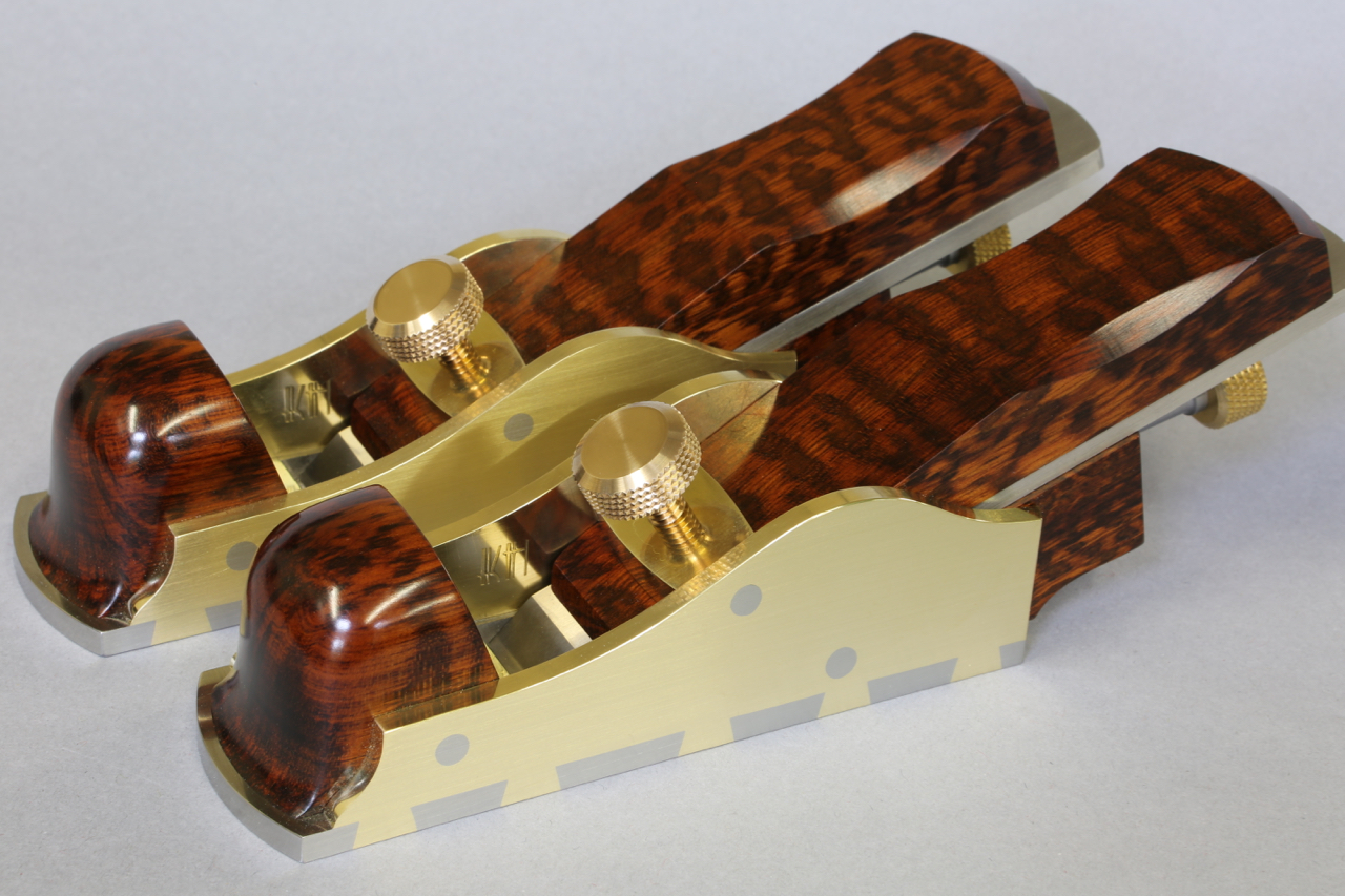
The A31 Thumb planes are now finished. The snakewood has come out really well
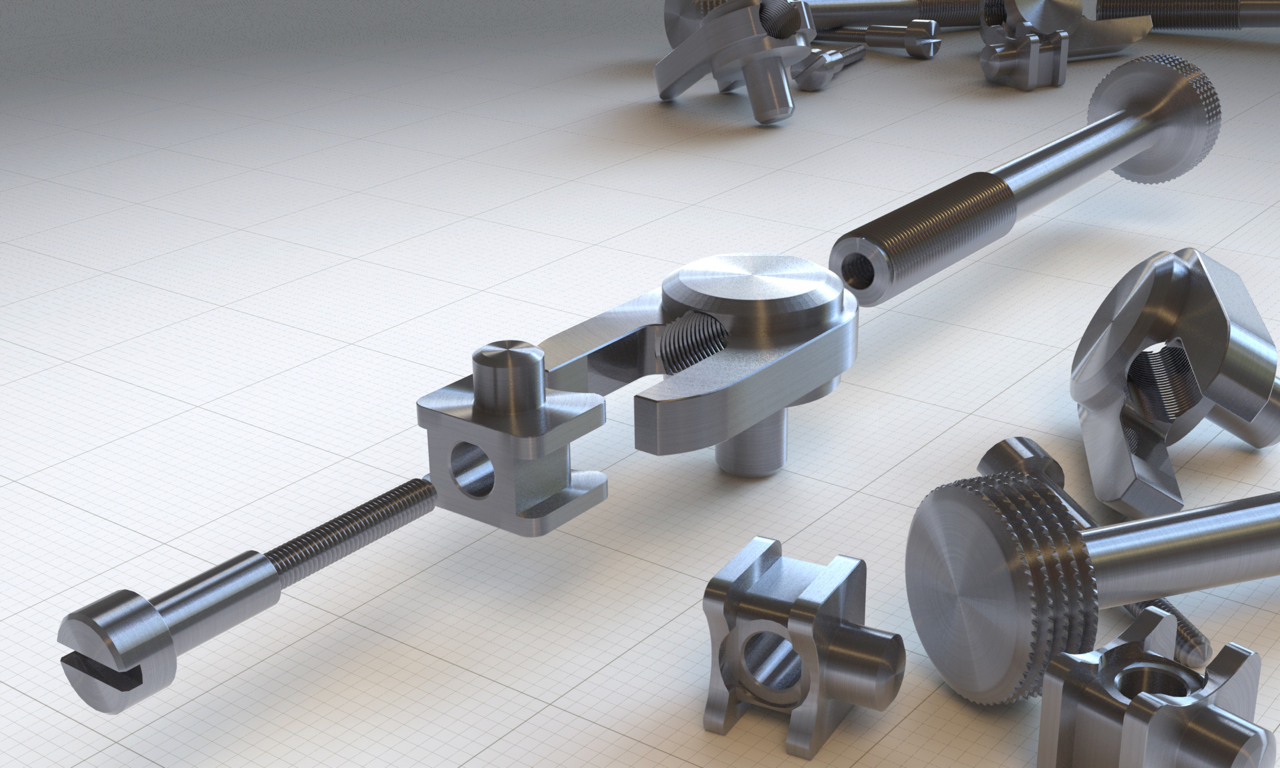
I want to show off some of the finer detail in the making of my adjuster components and the tooling used to make them.
These are for my low angle planes:
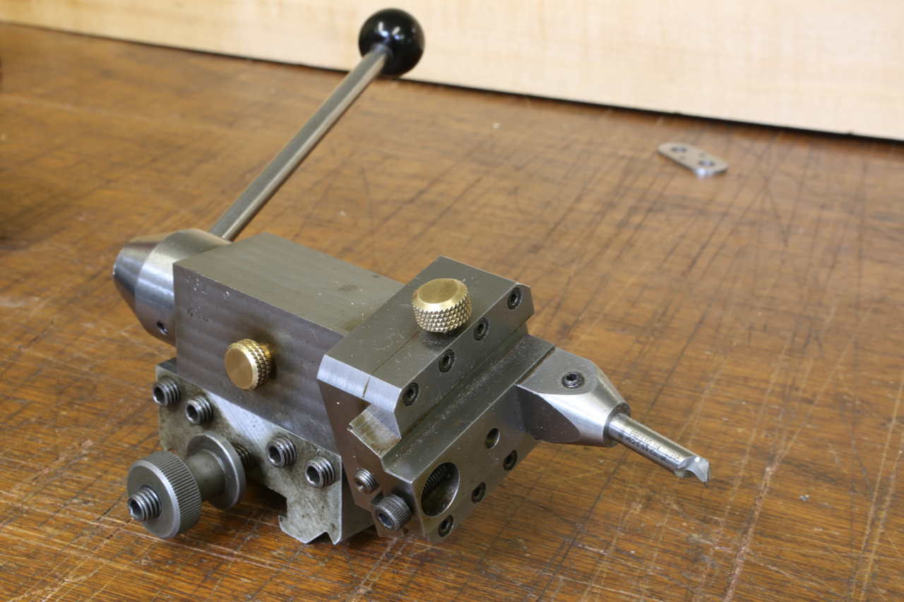
This is a ball turner I made 30 years ago in the days when I was very enthusiastic for making miniature locos. Over time it has been used a lot in the making of my planes.
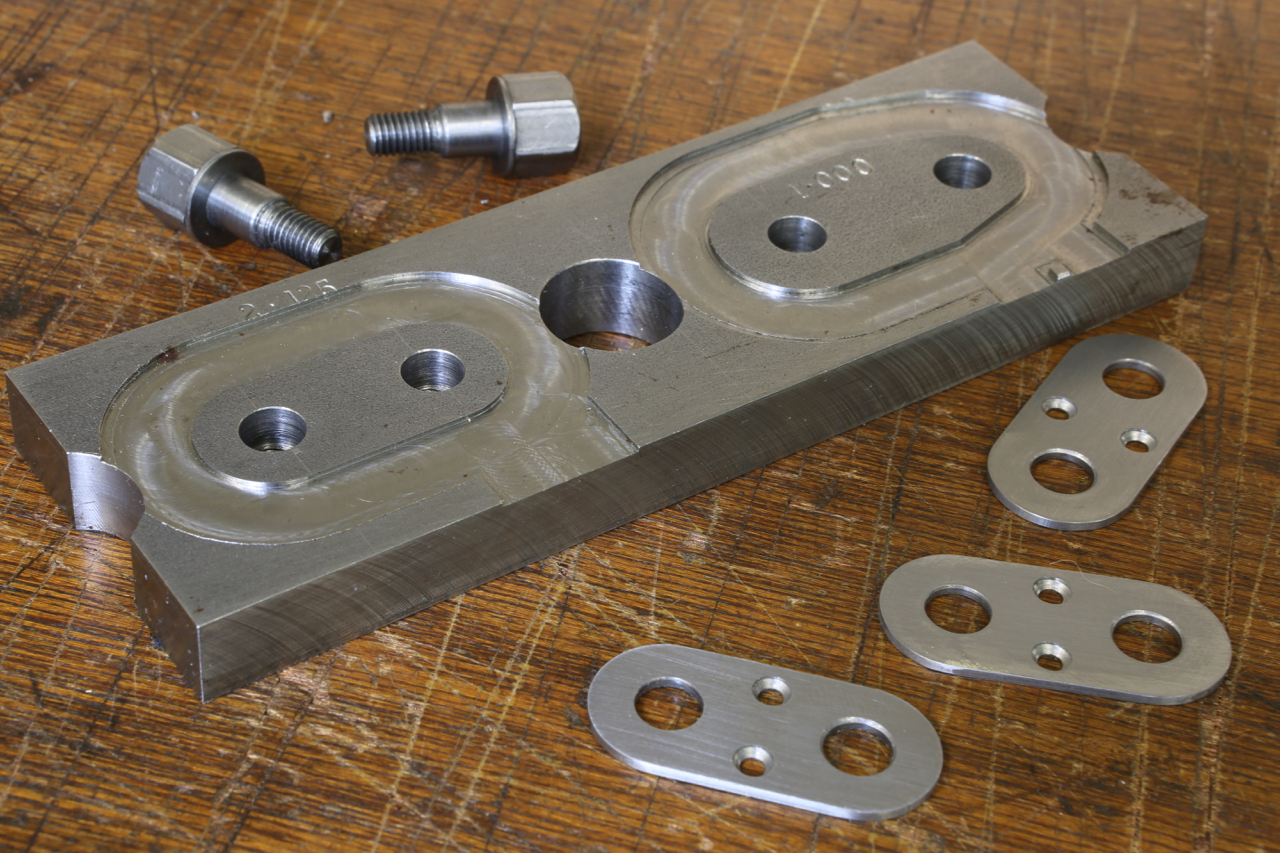
A fixture I made which is used for making my adjuster bases.
After the threaded stem and body has been ball turned a flat is needed so that it glides freely over the adjuster base and helps to orientate the blade driver. This is the flat after milling.
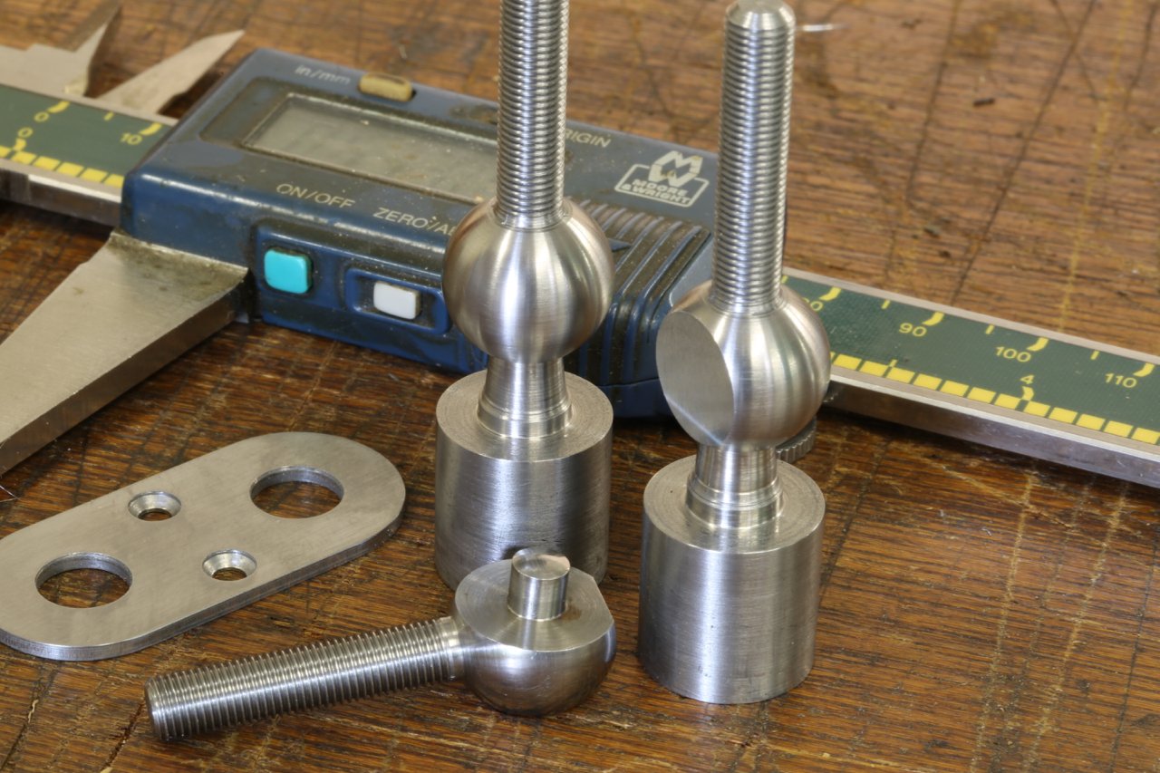
This is the blade drivers at different stages of their making. Two of which are still attached to their carriers, and one finished.
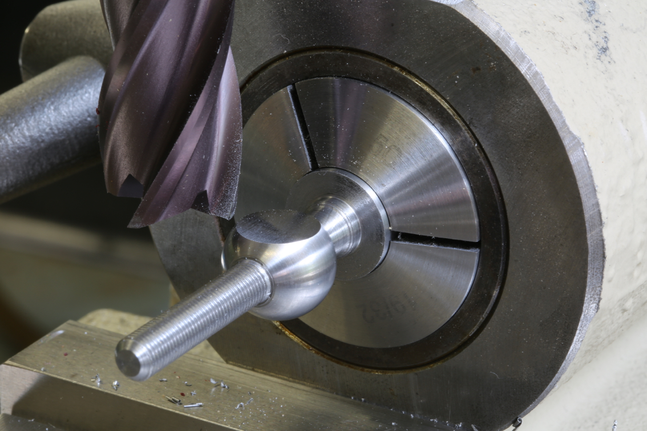
The last stage in the making of this blade driver is to turn the spigot on to its body. I had to make a special collet which was a little bit fussy because the spigot has to be formed 8 degrees from the perpendicular. Unlike the Norris counterpart it is all in one piece. Norris never went this far.
I have seen my work described in forums as analytical and lacking the warmth of a more rustic finish. However, my personal taste is perfection.
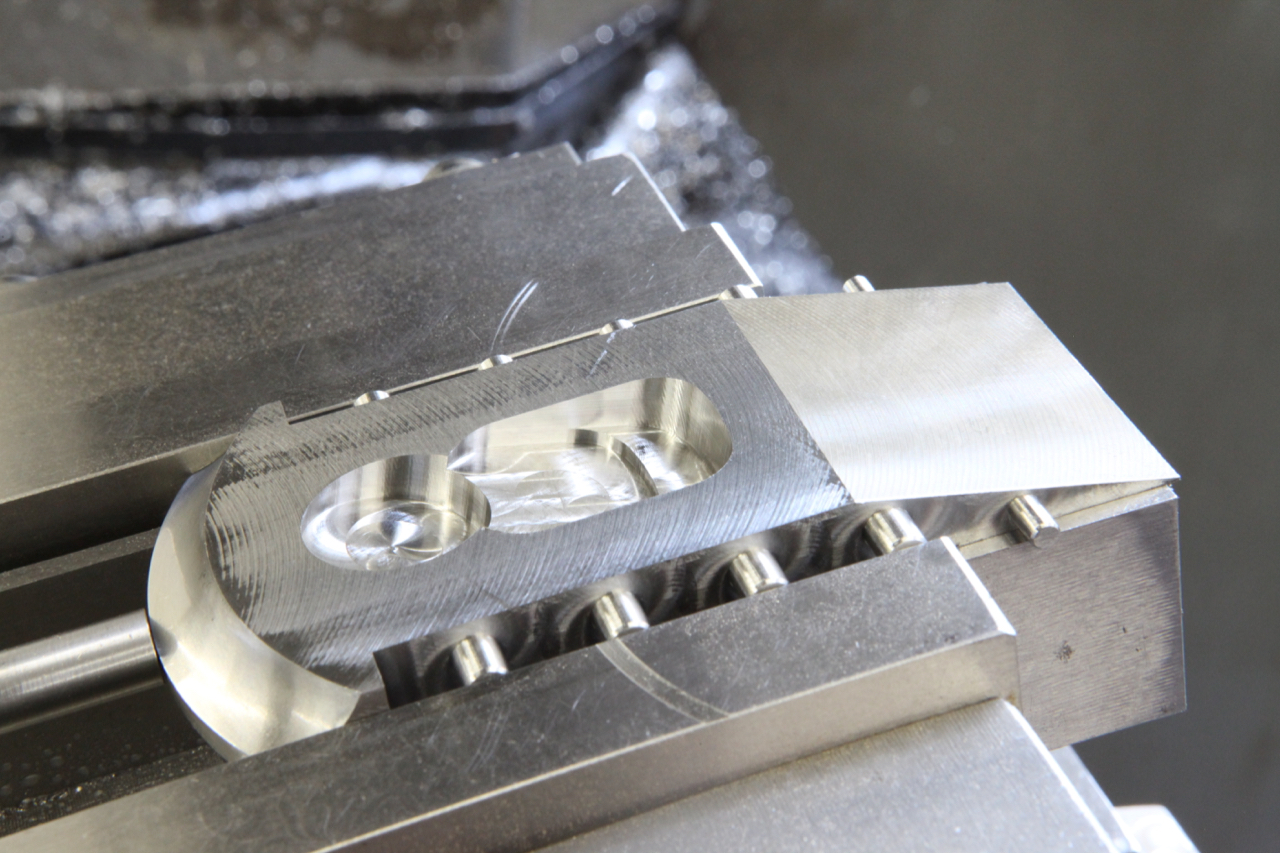
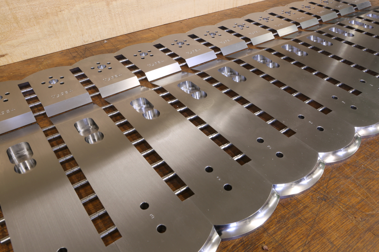
To achieve this perfection on the adjusters for my planes, work is intensive and the inletting for them is also time consuming. The system I use is on the CNC milling machine as the quality of work is essential. It is important to have an uninterrupted feed rate using state of the art tungsten carbide tools. This I think is more desirable than a hole that looks like it has been gnawed by a rodent ![]()
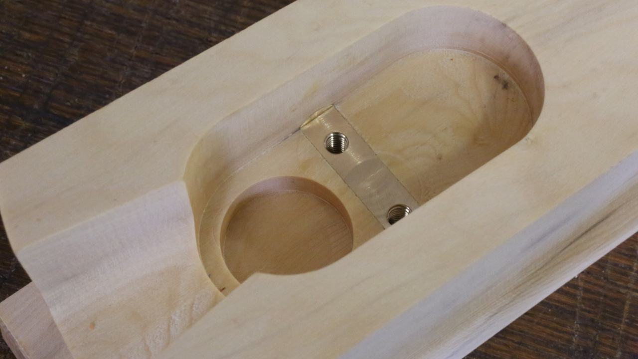
One of the boring sides of this detail. It is no simple polishing job as the valleys formed by the mill are very hard to smooth out.
It is a case of starting with a coarse abrasive and working down to 1200 grade and then I wrap a piece of denim cloth infused with metal polish for the final polish.
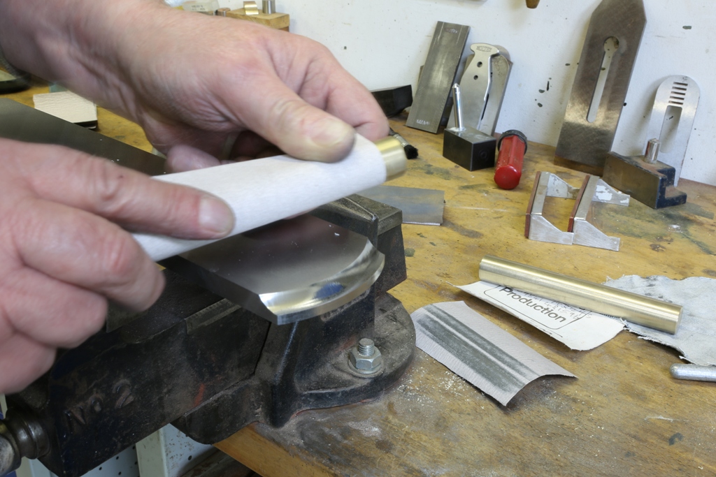
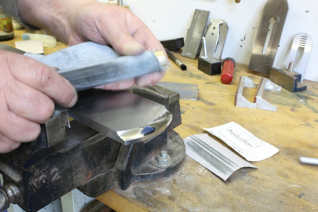
That is a reflection of my magnetic tool rack which looks like a row of vertical scratches.
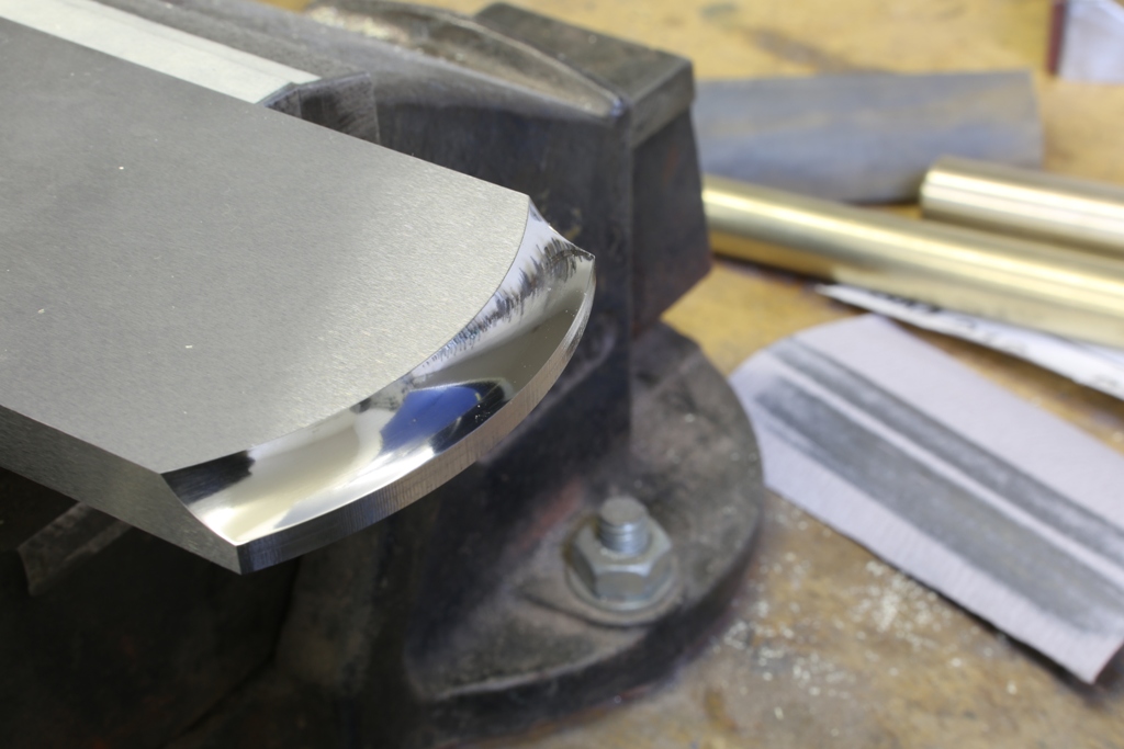
It seems odd doing polishing at this stage but it is the sequence which I choose to do the work in which gives me the finish. When all the riveting and adjuster recessing are complete I can surface grind the inner parts so everything is sharp and pristine.
Somebody on a forum described my work as being clinical and having no soul, maybe he is right and it is dammed hard work to keep it up ![]()
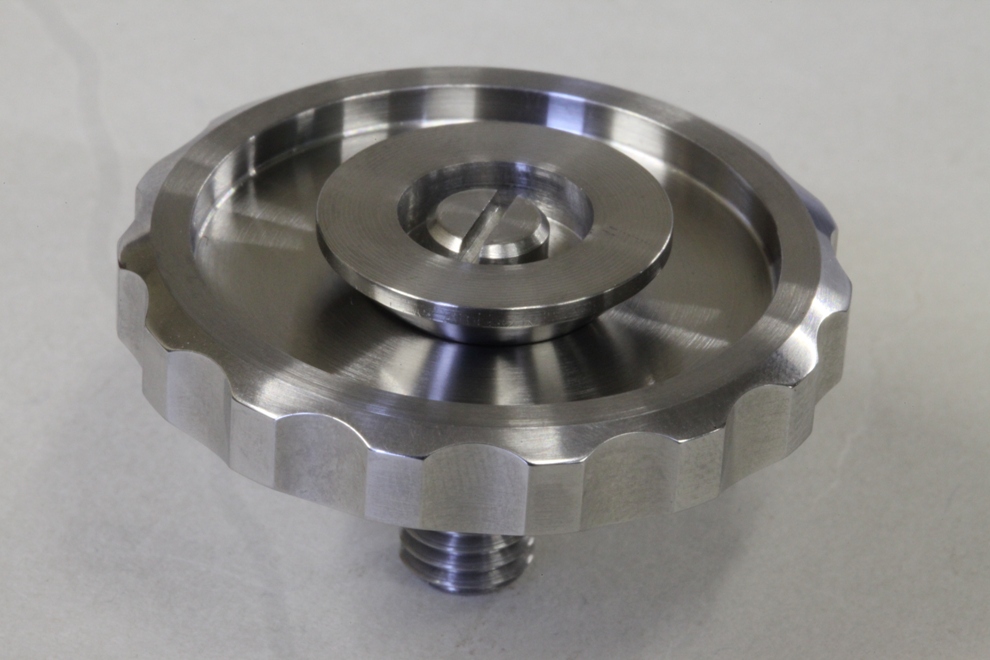
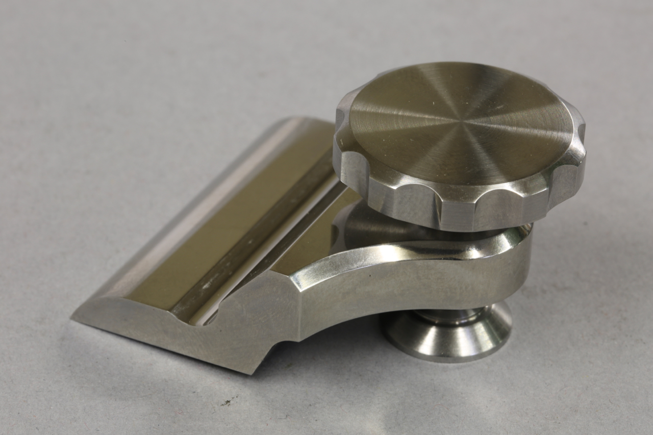
After several weeks of design, trial and tribulations, the thumb wheel in stainless steel is finally complete. New designs and ideas are always time consuming.
This picture shows the thumb wheel inverted and assembled with the floating spherical washer (the washer does not appear to be central on the photo as it is floating). This works with the matching spherical depression in the underside of the thumb wheel like a ball and socket; evenly spreading the load over its area, helping to eliminate any lateral movement on the blade as you tighten down on it. It also helps to evenly distribute the pressure throughout the blade bed reducing body distortion.
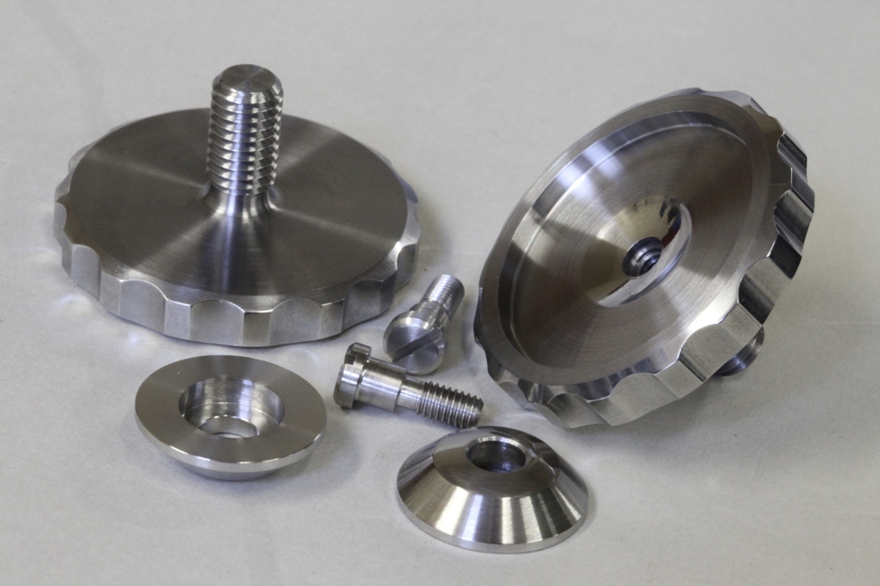
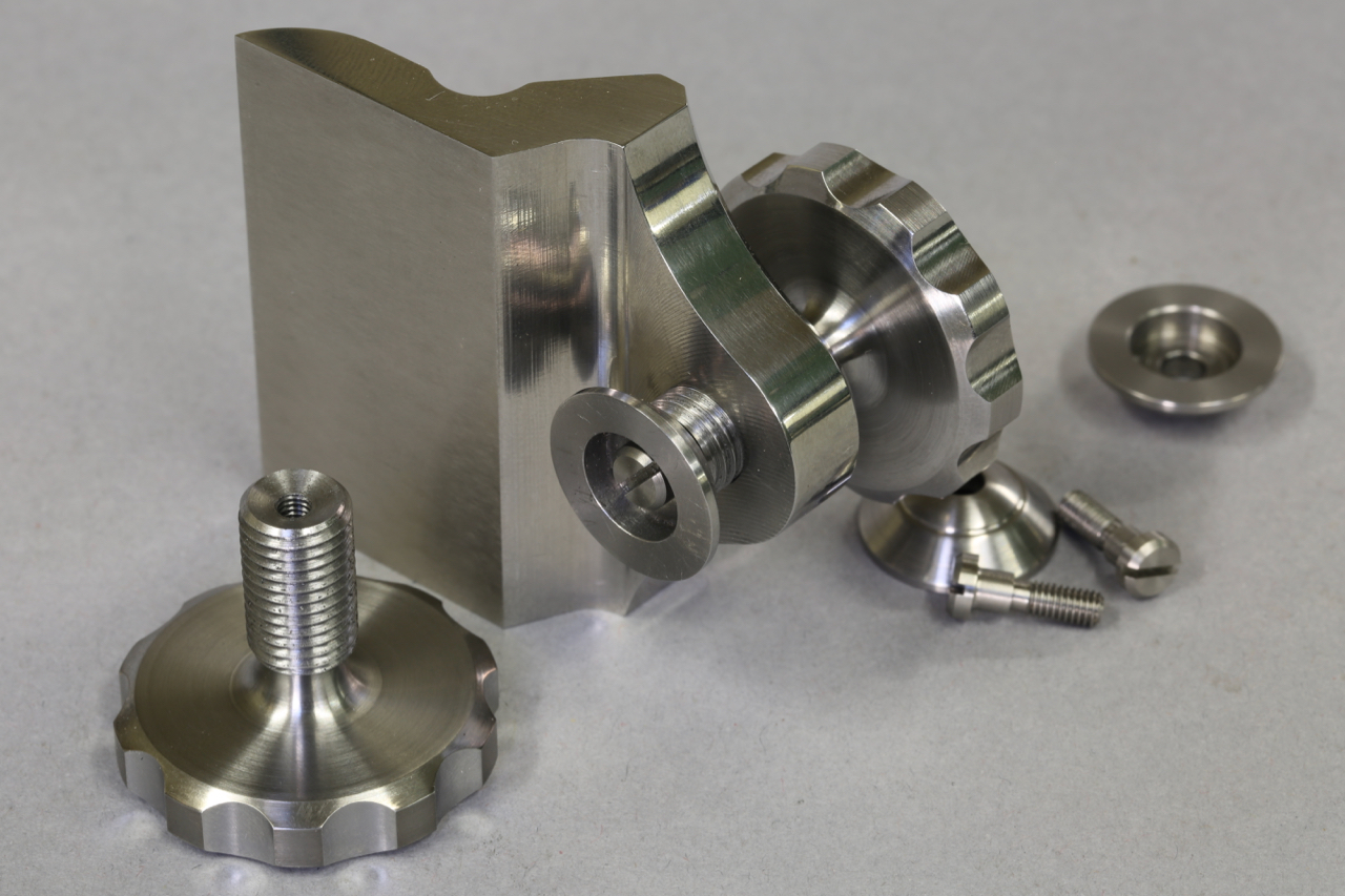
These are the three components making up the thumb wheel. I have changed the grip arrangement on the thumb wheel and screws. I dislike the fact that a lot of knurls fill up with dirt. Aesthetically I find this method, though labour intensive, is more pleasing and feels comfortable on the thumb/fingers.
I would like to emphasise that, as always, all my components are hand made, in house.

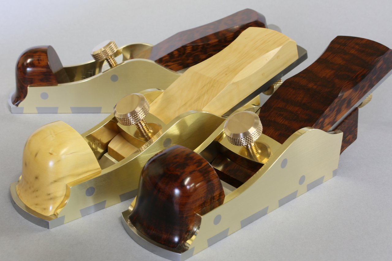
Selected wood for my next project – A31 thumb plane (probably the last batch)

Best part of the metal work well on the way
Powered by WordPress