These are some renders of my A1 panel plane that Adam Willis has created for me
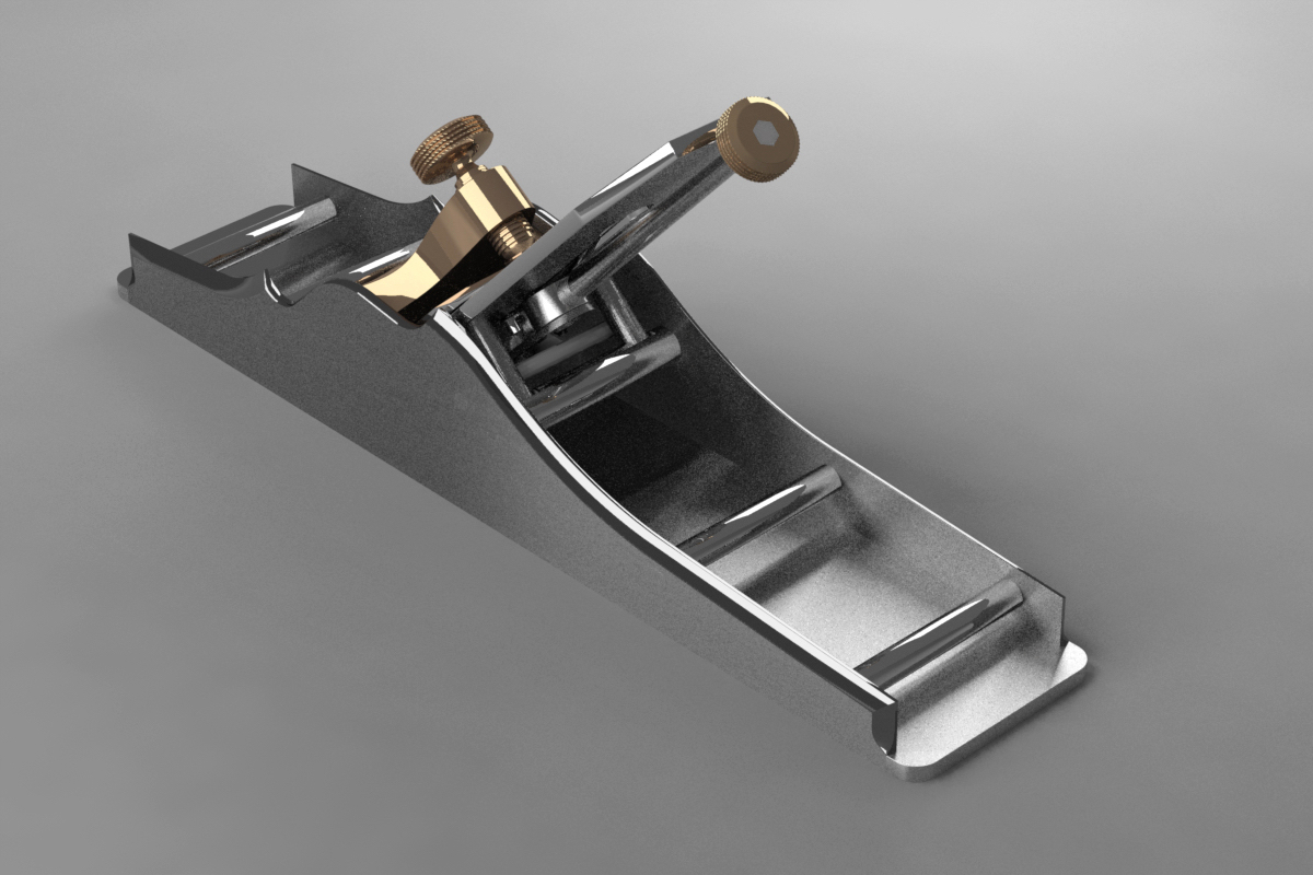
These are some renders of my A1 panel plane that Adam Willis has created for me
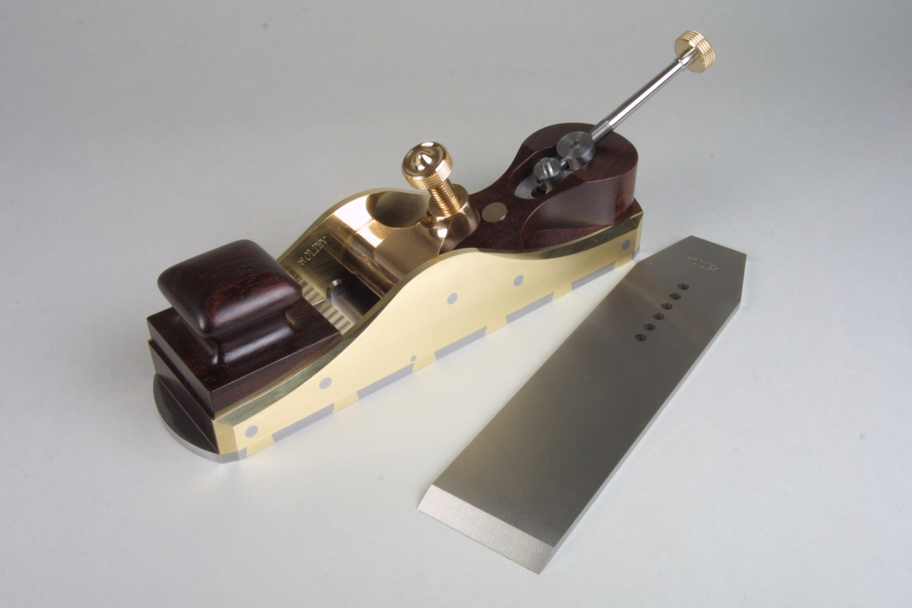
Holtey improved pattern mitre plane, Norris and Spiers style. But with an adjuster
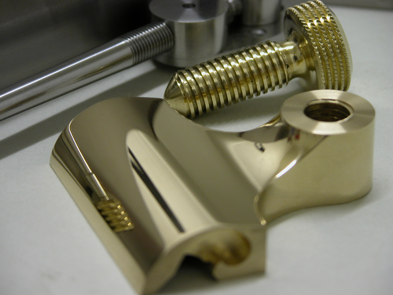
Lever cap for improved pattern mitre plane
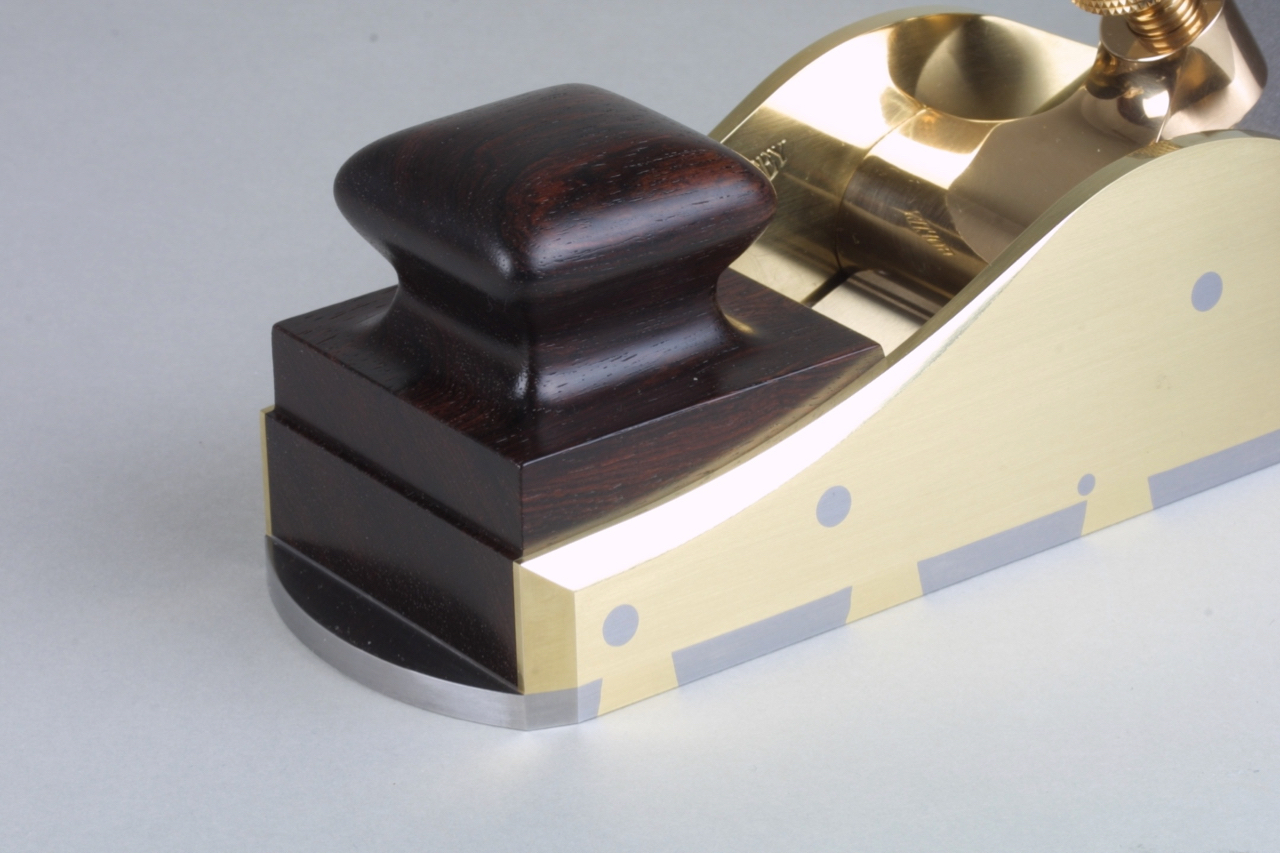
Improved pattern Mitre plane showing bun
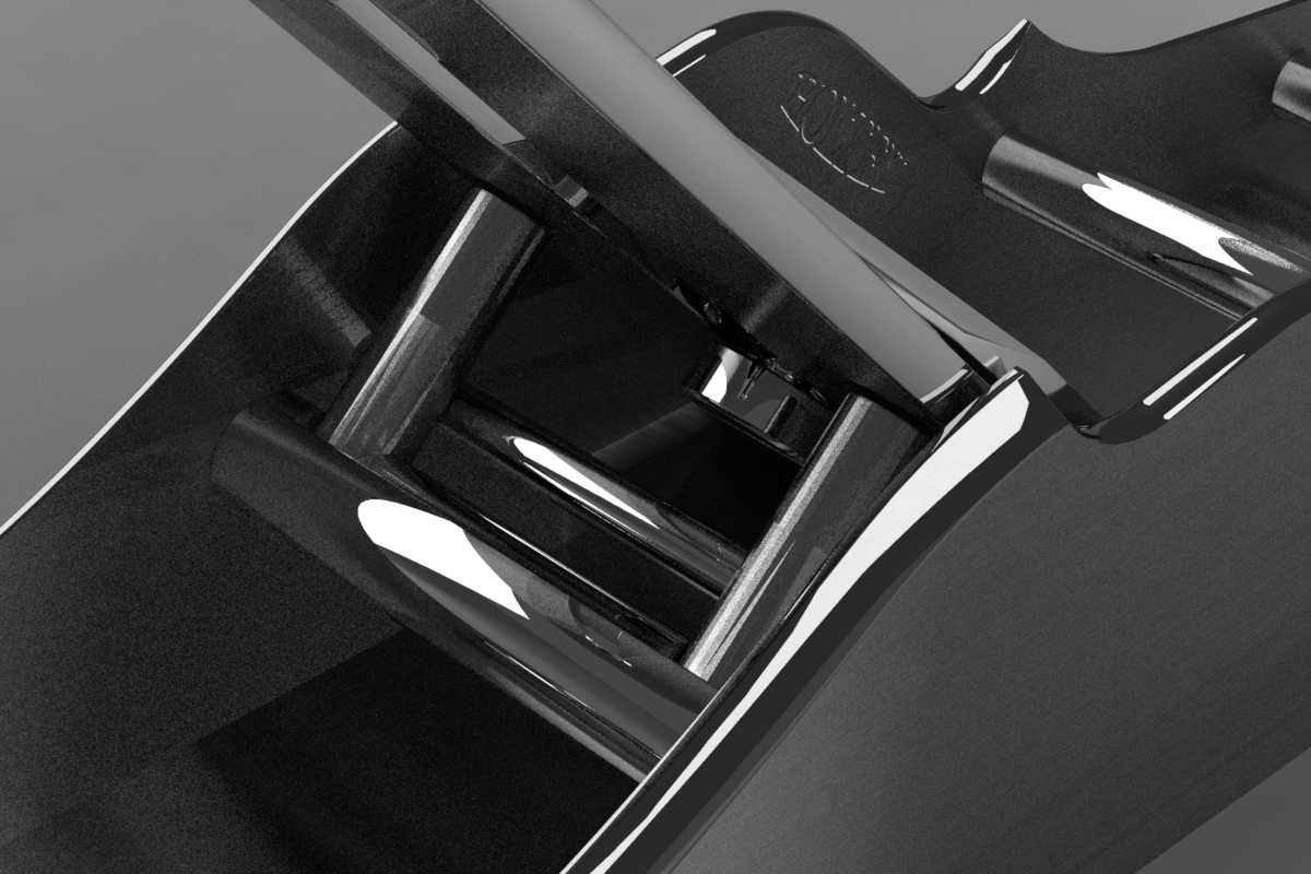
improved pattern mitre plane with adjuster, rear view
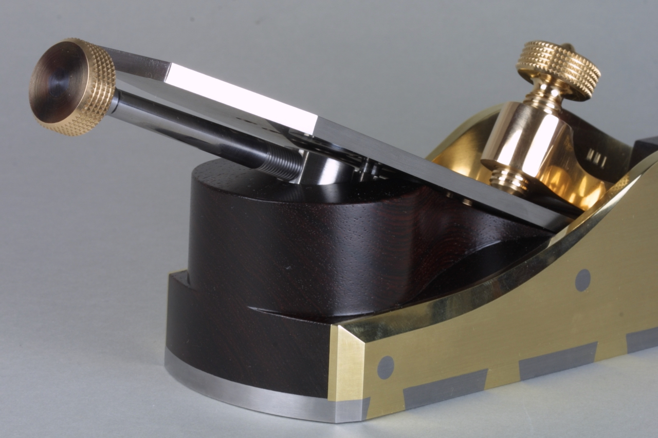
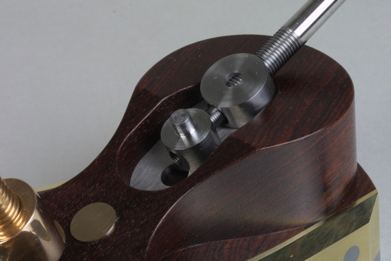
showing adjuster in it’s recess
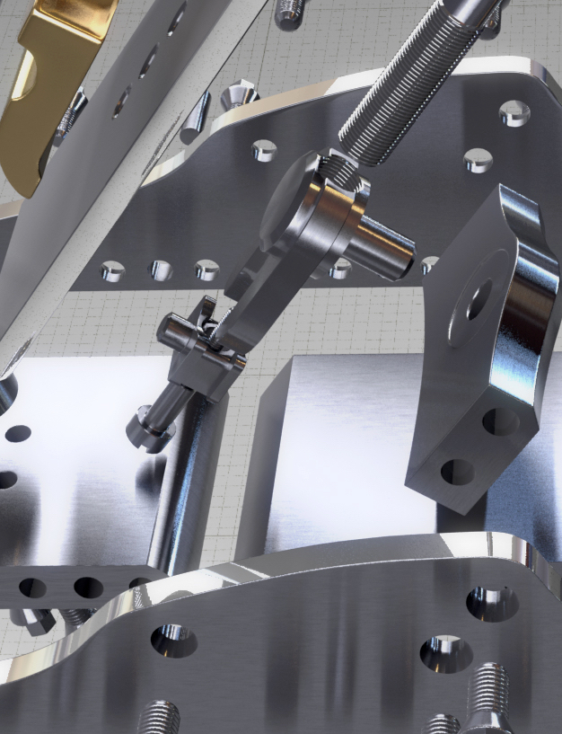
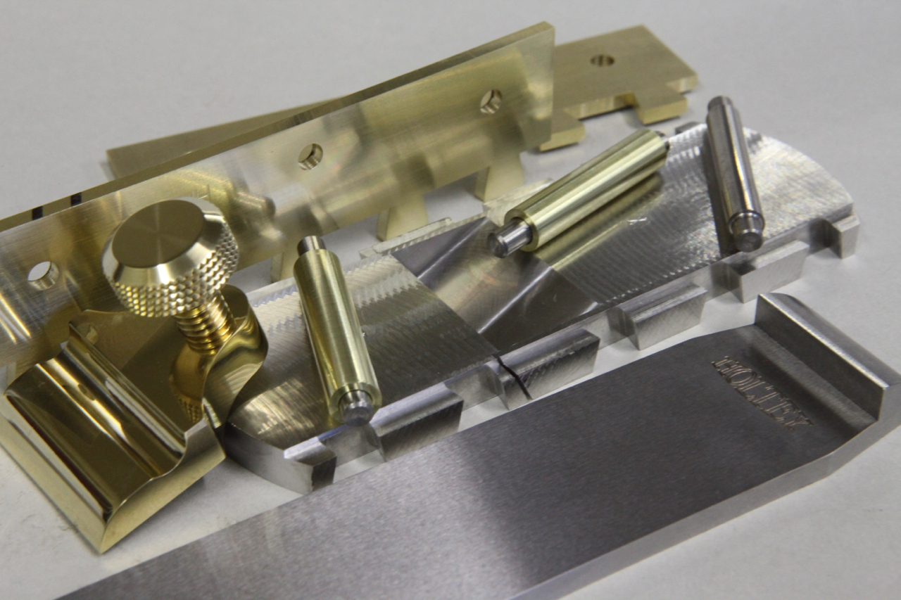
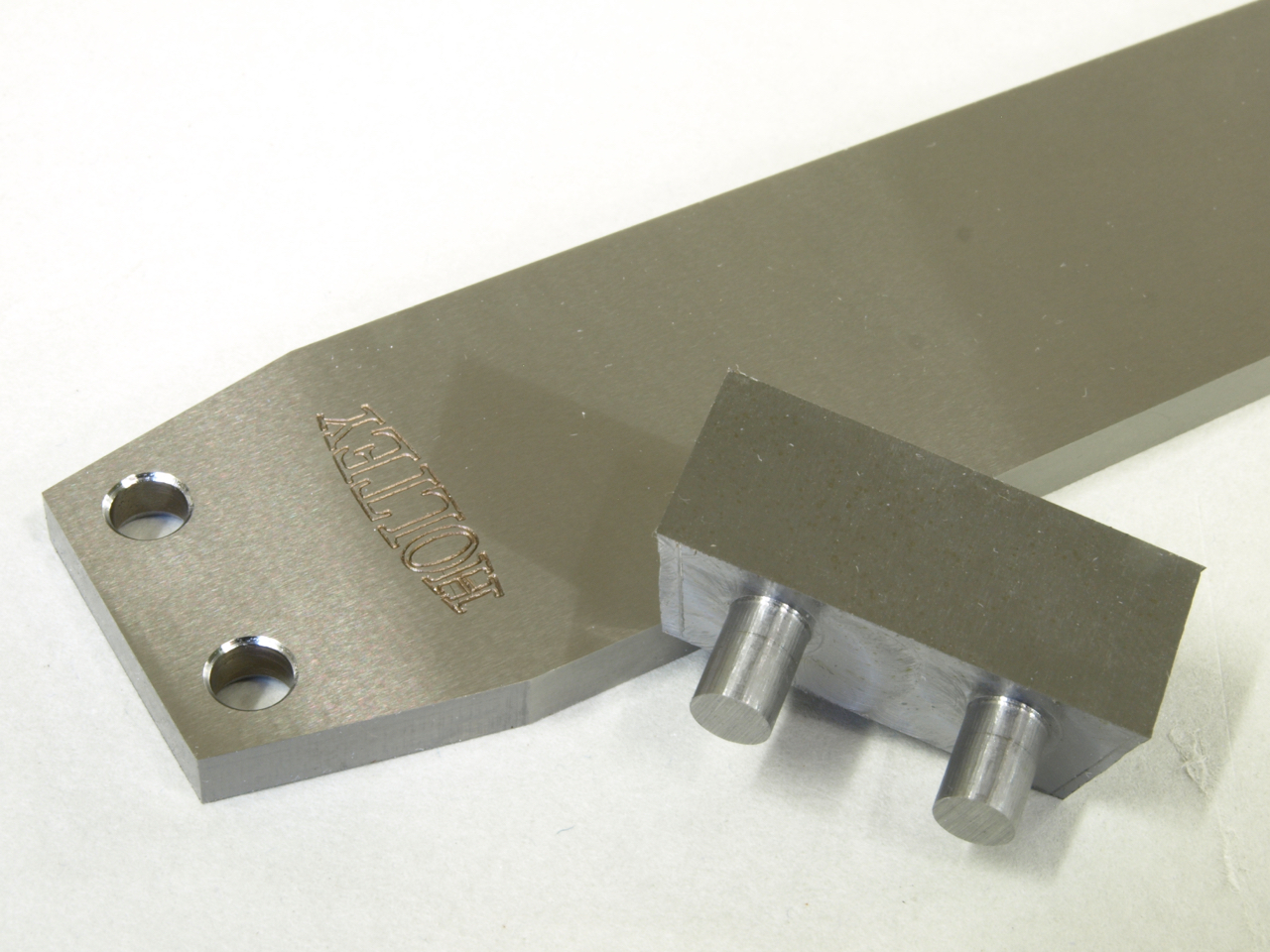
No 10 small smoother plane. Metal component parts
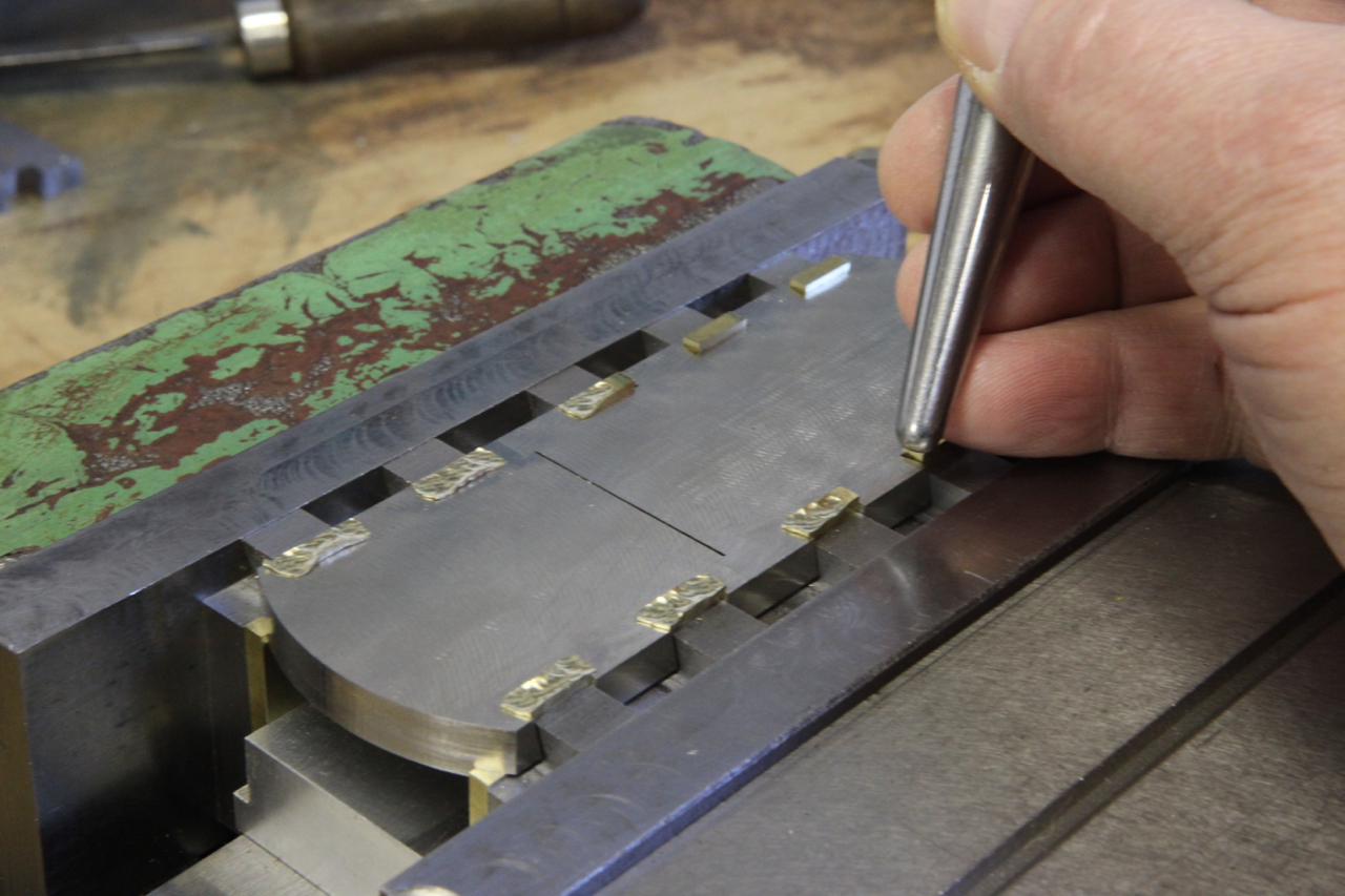
peining the dovetails showing the forming tools
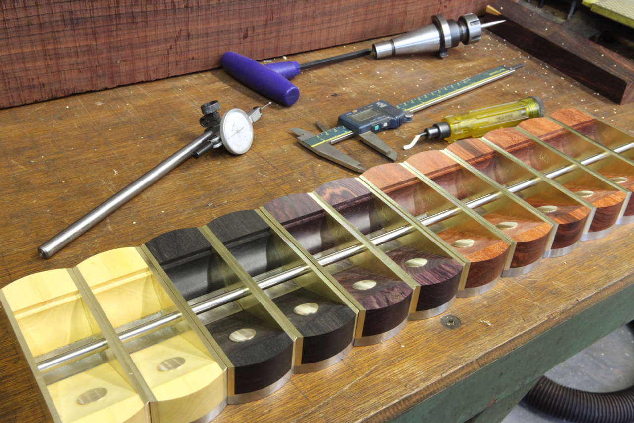
Showing various infills
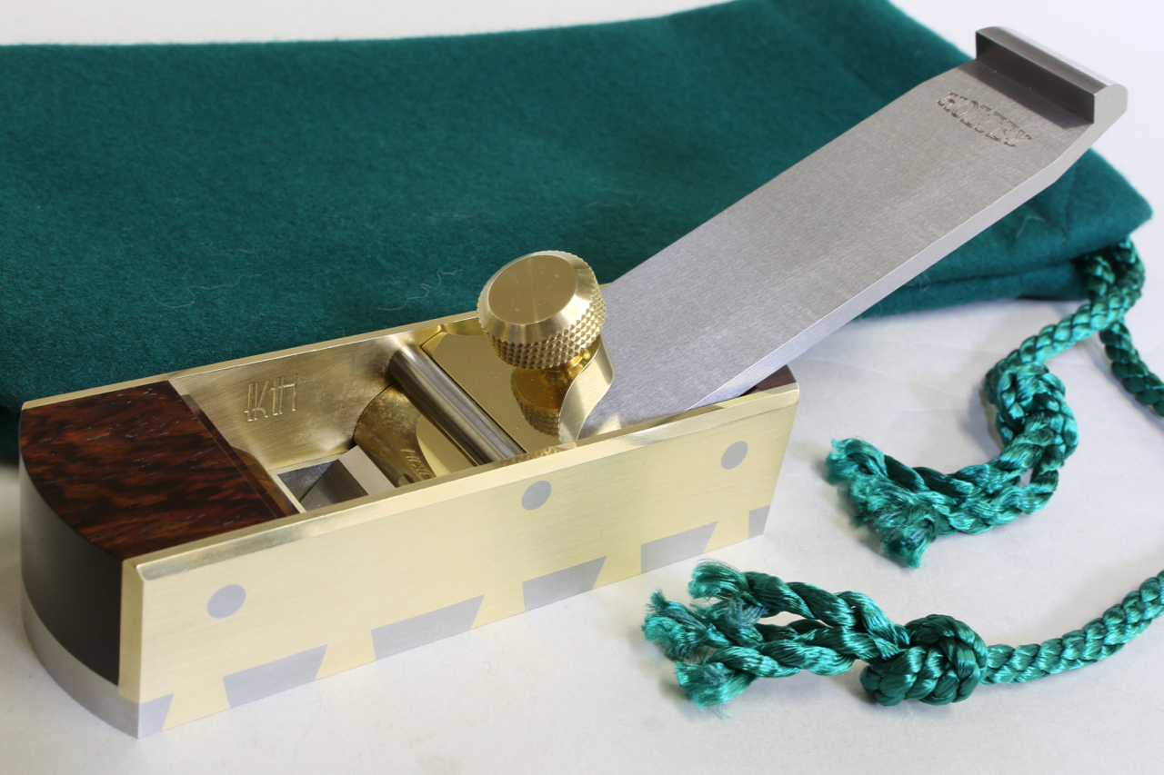
The finished No 10 smoother plane
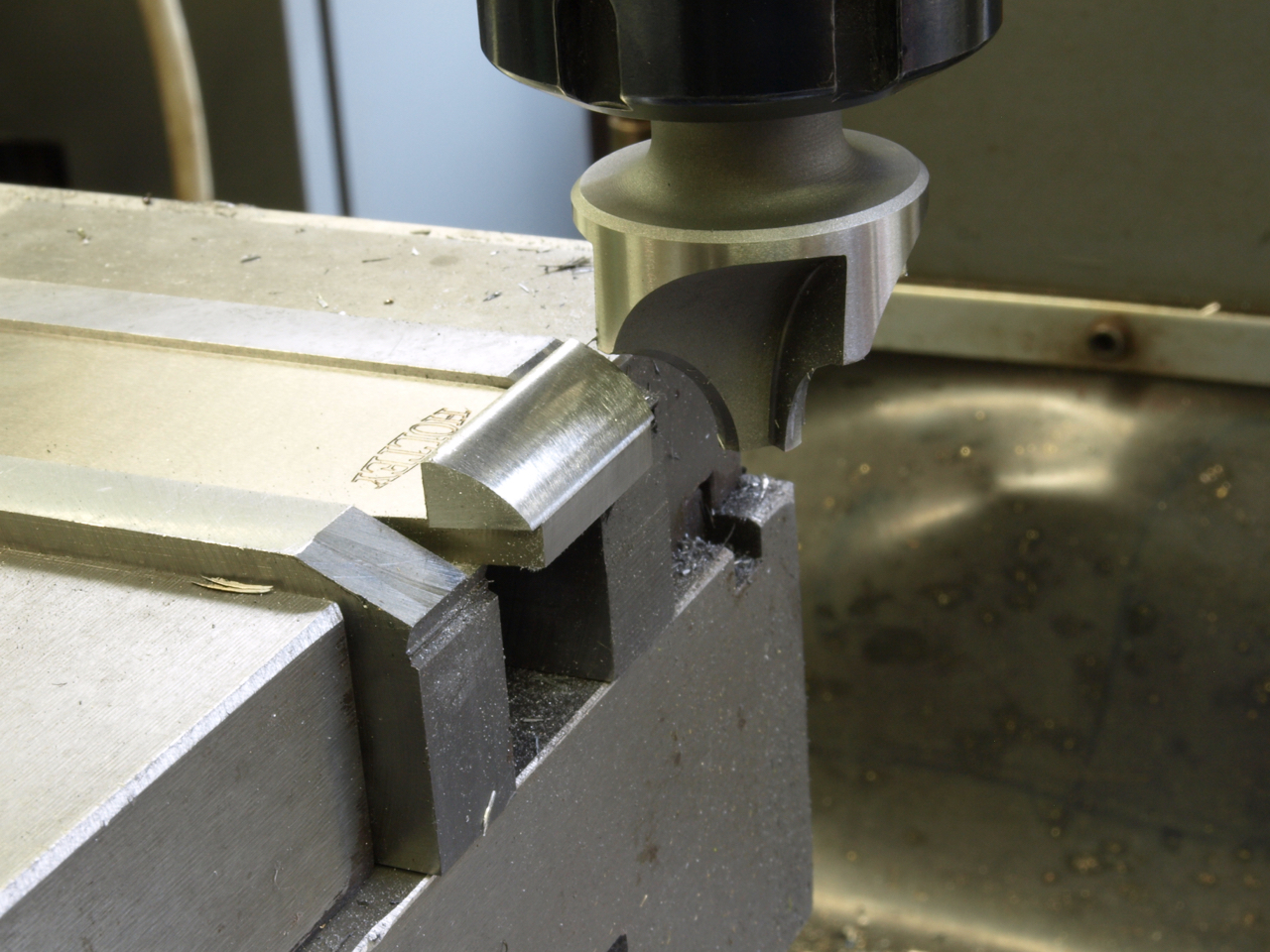
No 10 small finishing plane. The relationship between the sneck piece and the blade.
The blade is rejigged so that the milling cutter can follow the original contours of the facet.
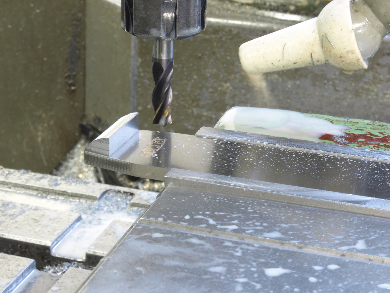
The sneck form is milled after the integral rivets have been peined with a fly press. The blade used at this stage has been hardened and surface ground. The hardening is the only item which is outsourced to a heat treatment specialist.
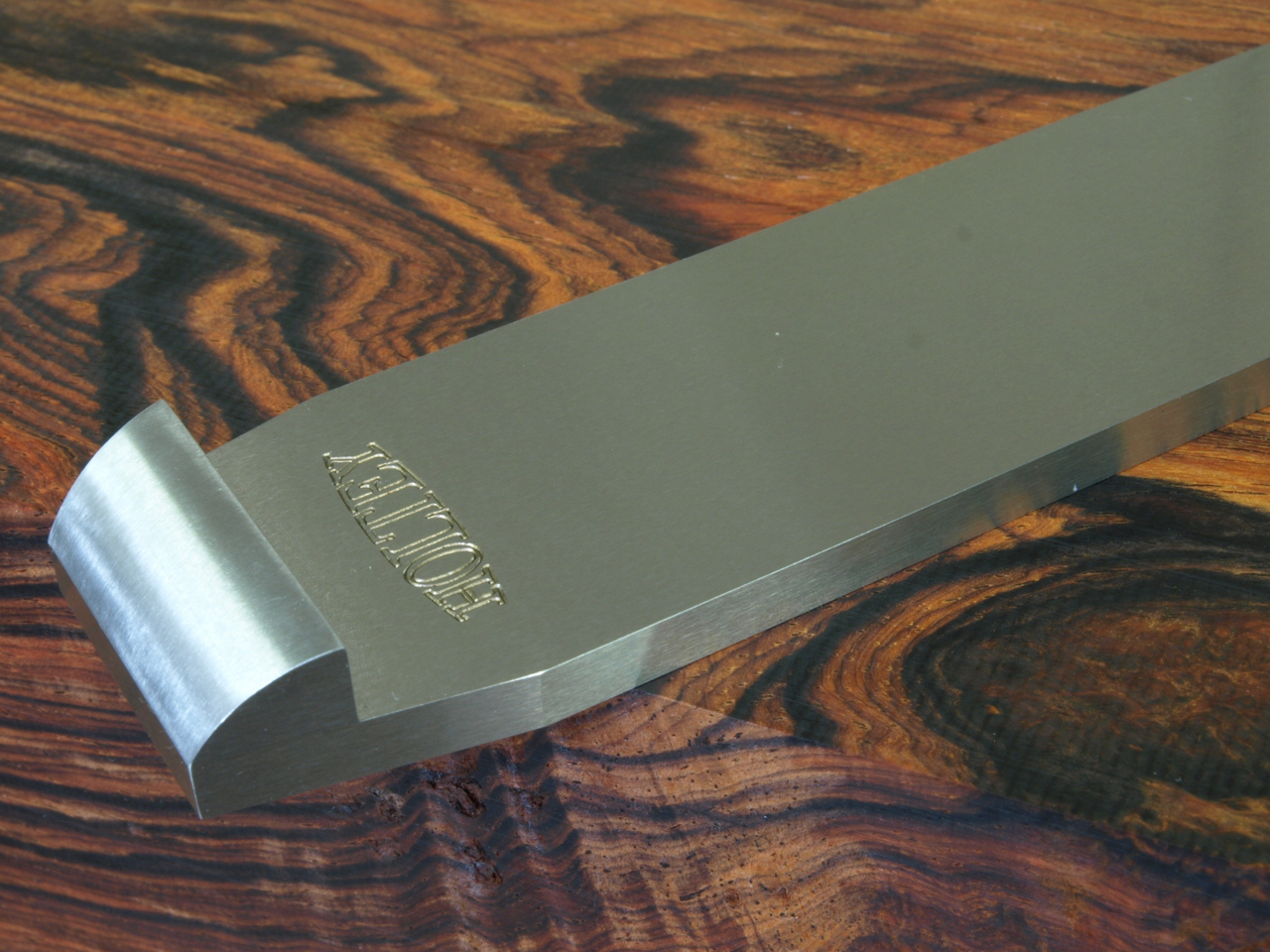
The finished No 10 blade
No 10 smoothing plane. I have chosen this plane for its simplicity as an insight for the amount of work and effort that goes into this plane. I will tell its story over the next few postings.
Starting with the blade drilling and facet forming
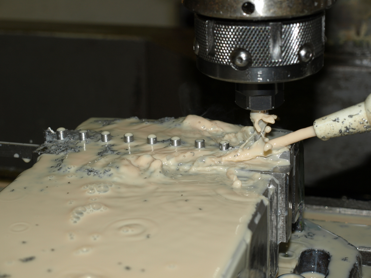
Integral rivets being milled in situ on a bar strip to be cut up into individual sneck pieces
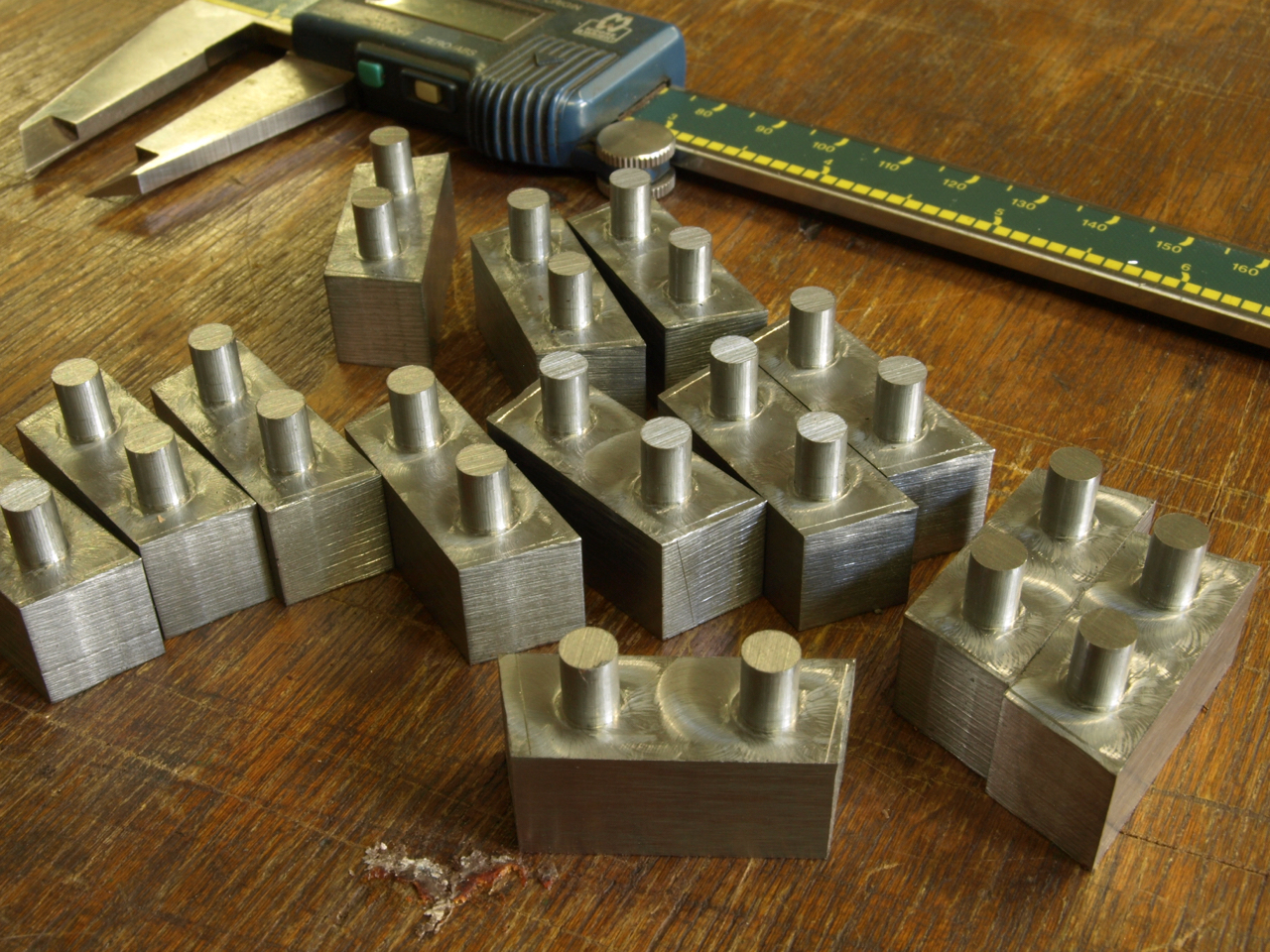
Sneck pieces shown after being cut into individual pieces
Some photos of the No 984 panel plane
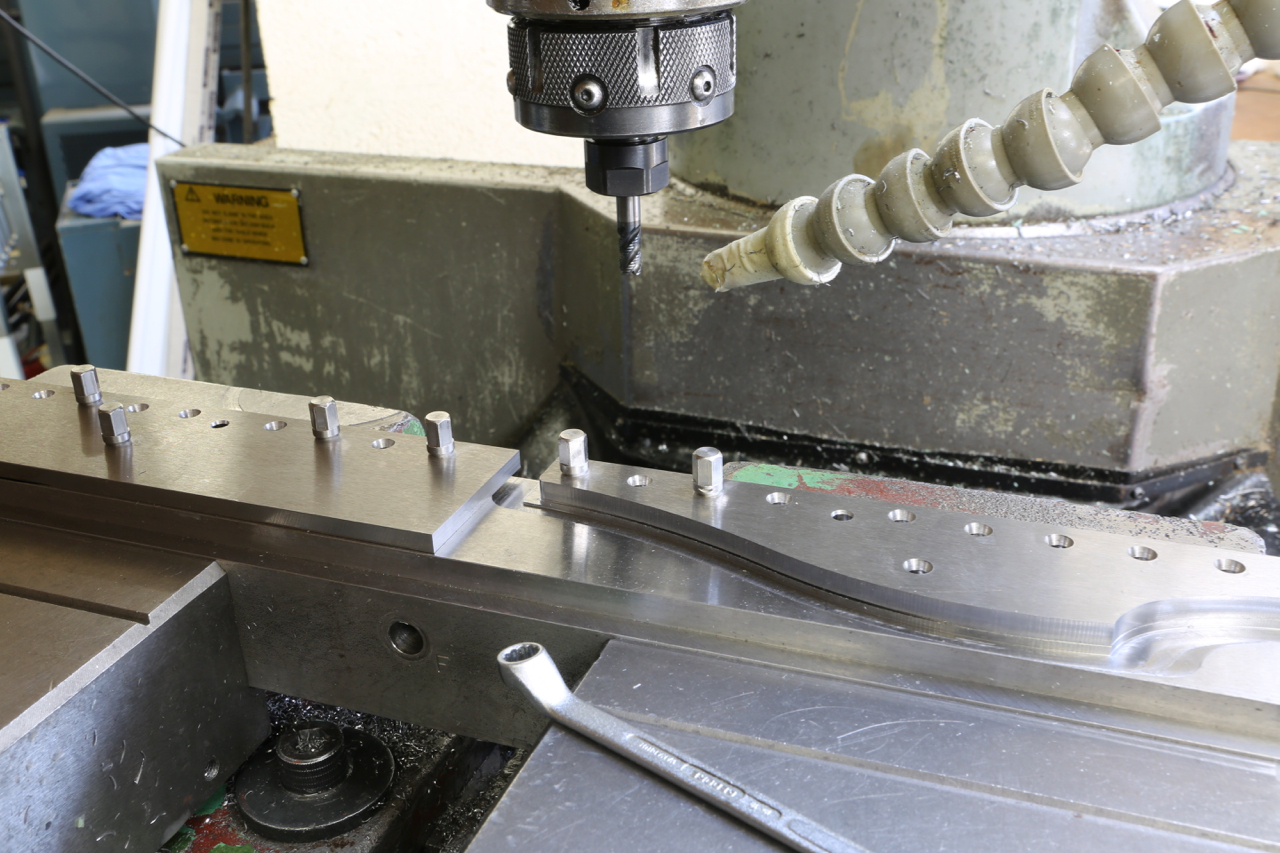
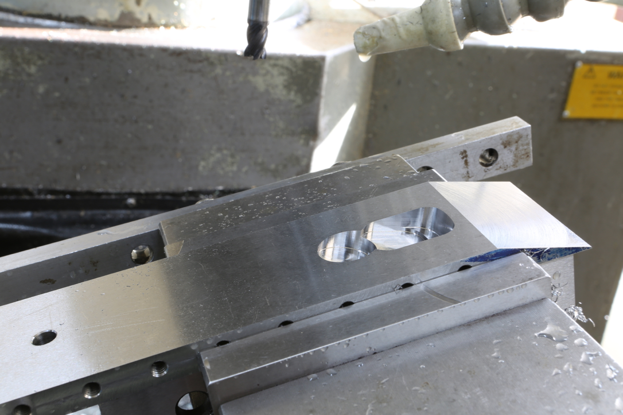
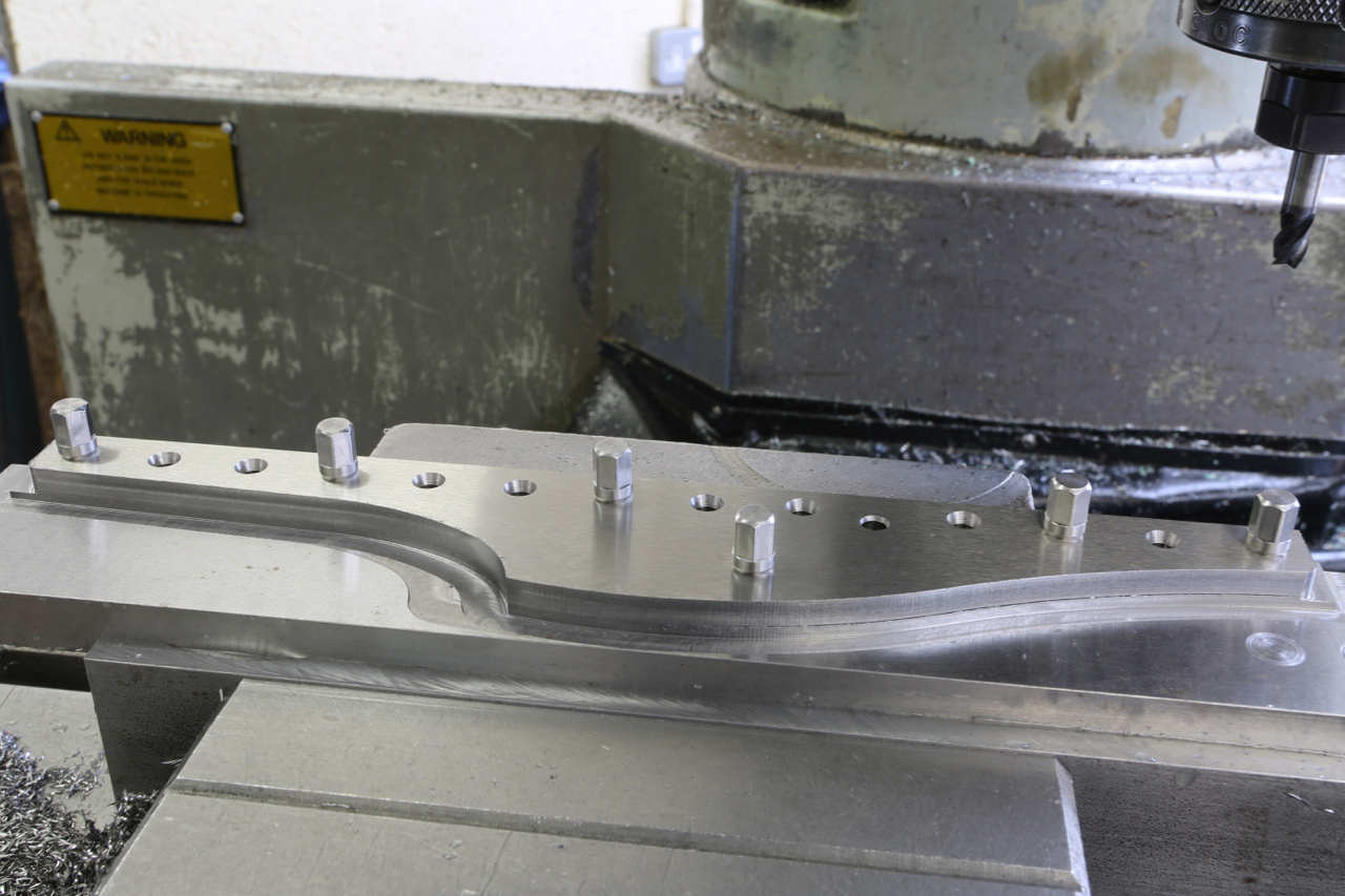
No 984 panel plane sides being routed on milling machine – no water jet or laser here. All work in house.
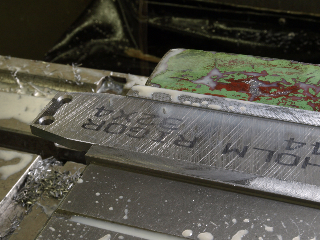
No 984 panel plane milling of blade bed and adjuster recess.
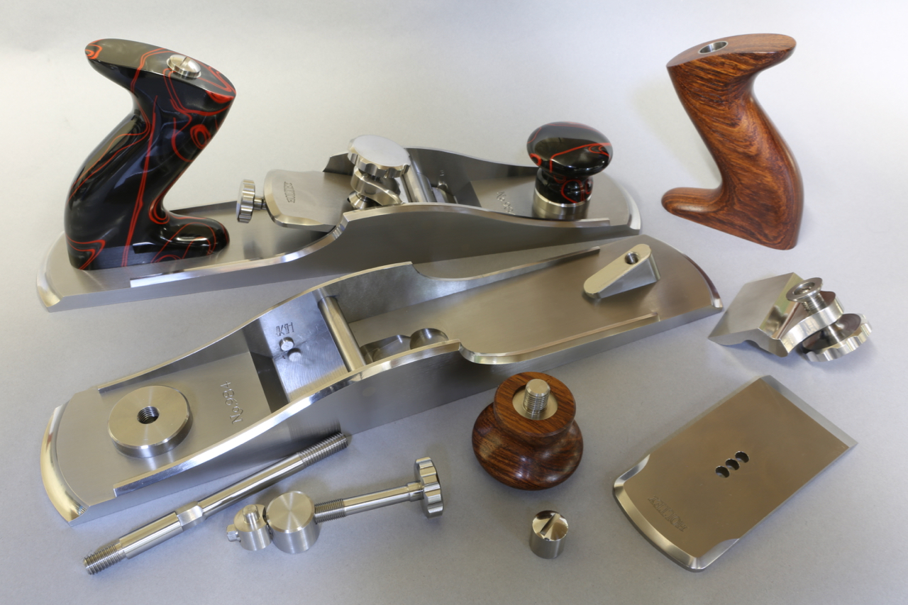
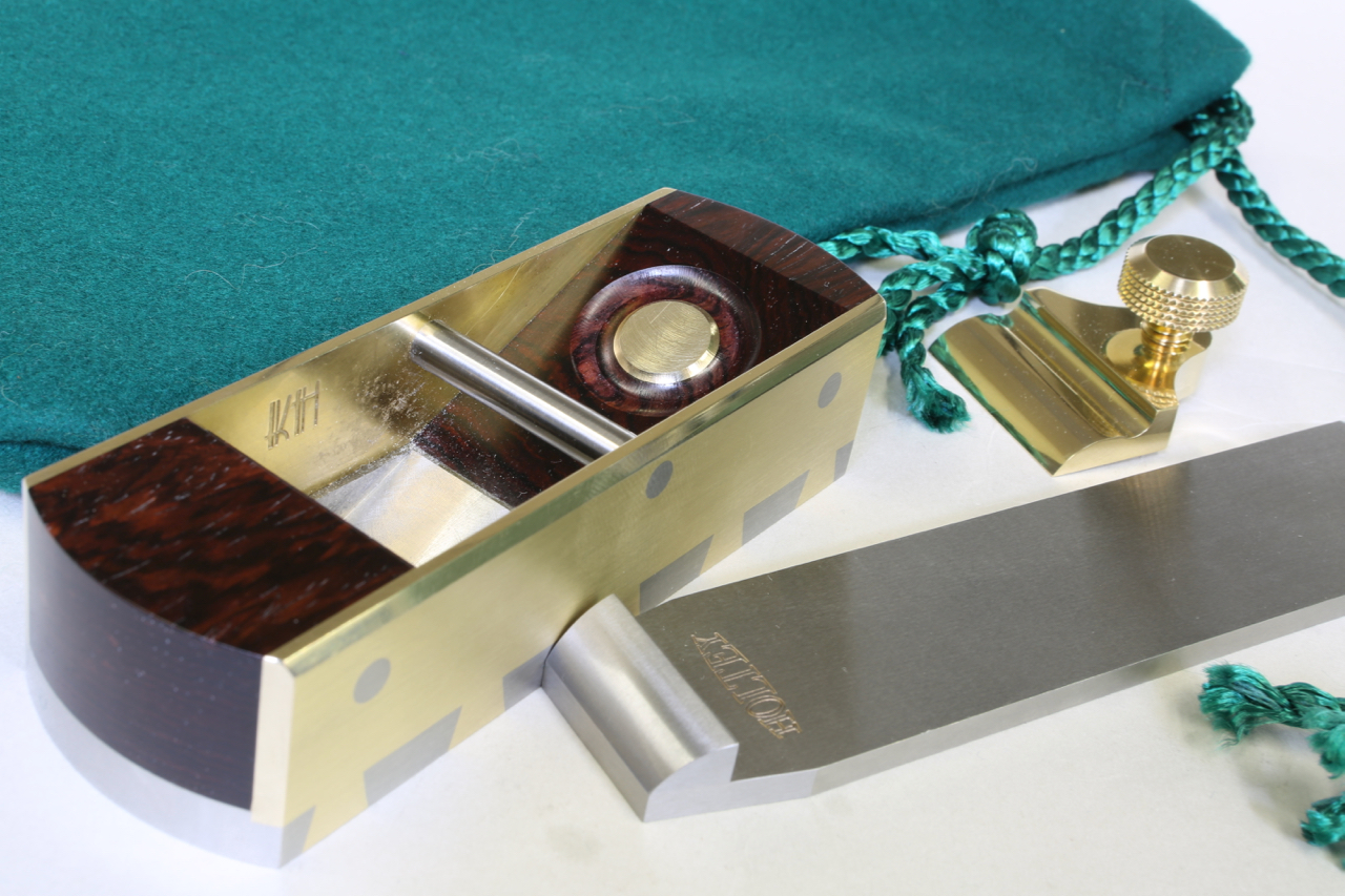
No 984 panel plane. Lever cap, adjuster and bun are easily removed without any tools
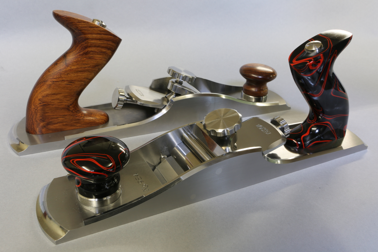
No 984 panel plane with acrylic and rosewood ( honduran rosewood) handles
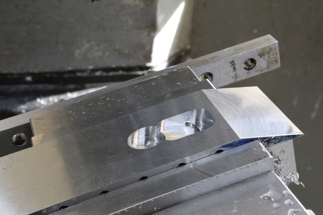
With the sides prepared I can now make a commitment to the sole of the plane. i.e. mouth position and adjuster recess. This is a critical time which I would prefer not to get wrong, in fact it can get scary. The excitement level gets stronger as things progress.
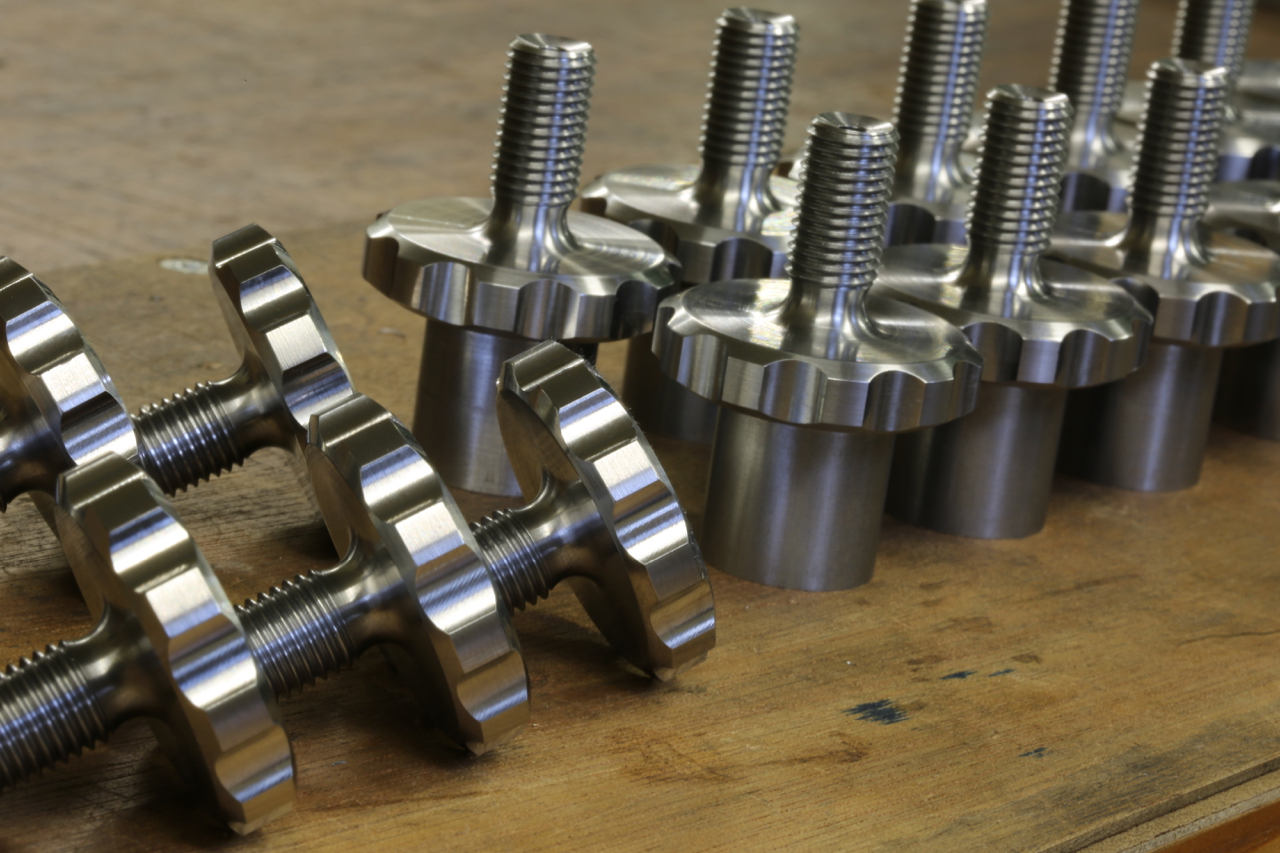
I am making a variation of my No 984 panel plane to use up some components, it will be designated No 984s, there will only be a small number . It would be a shame to waste them especially these thumb screws.
I have said little about this variant of the No 984 panel plane. It is to be designated No 984s.
There will be some differences as well as the decrease in length.
With the bottoms only being half worked they are now shelved until I have completed the sides.
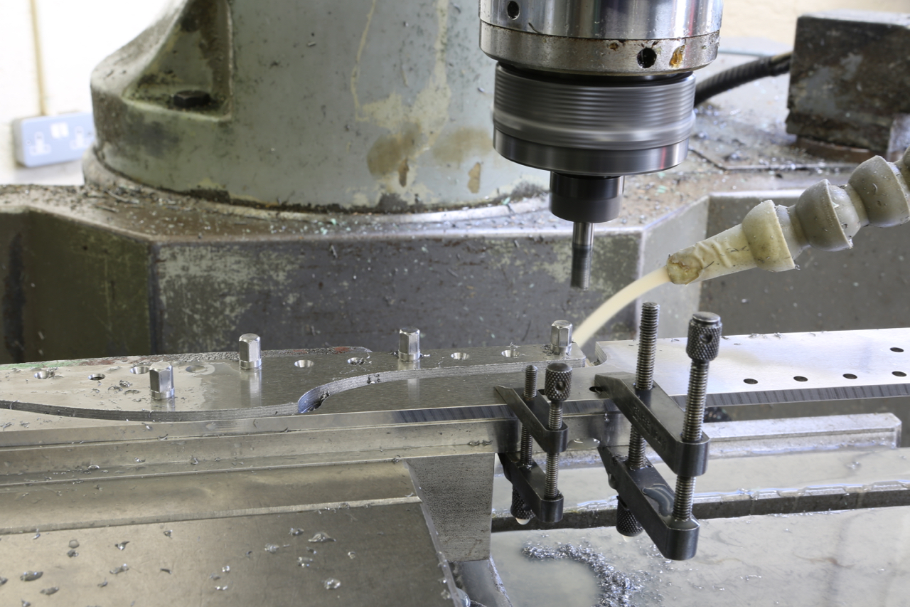
I have deliberated long and hard over the design of these sides. I have now decided not to chamfer them. This is by no means an economy and as you can see from the photos the chamfers could have been completed there and then and that would have been the end of it. I have taken a leap of faith and trusted my instincts because I feel that leaving the edges square will work better with the other changes. The profile looks more sharp finned and streamline than the chamfered version. It is all down to waiting for a finished plane. I know it will be the proverbial ‘brick built shithouse’ but this is what I wanted.
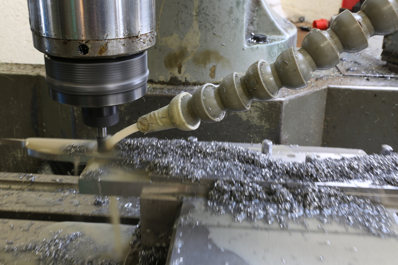
The middle picture shows the stainless steel side being routed with an 8mm ripper which surprisingly went through very quietly with no effort or noise. A single cutter lasted the whole job and still has life left in it. I have left the swarf in for the picture to show the amount of material removed.
Powered by WordPress
Dovetailing v peining v screwing v in situ doweling
Lets start with dovetailing. The effectiveness of a dovetail must be compounded so that you show a dovetail form on two sides. That means you are going to have a void on one side which will need filling. You will need a bit of extra material left on the ends of the pins and dovetails. This means you have to move the metal around by peining to fill the voids. You have already picked up on my pinch formers and the clamping plates which are made to fit inside the dovetails. All that peining is going to push a lot of things around. Another problem is that there is going to be pressure along the line of dovetails which will then convex the sole. If it doesn’t then you are not peining it hard enough, you want to stuff as much material as possible into those voids. There are good and bad dovetails around. Once everything is all snug and finished there will be a lot of material to flush away and the bottom needs to be flattened on the mill. Also the sides need to be treated in a similar way. I don’t know how far other people go with their dovetailing but this is how I do it. You will notice how true each tail is. All lines are straight and sharp. The former is kept parallel and is the same width as the pinch sides of the bottom. In my language this is a F******g load of work.
There are two other options. One of these is to form dowels in situ on the bottom which has to be a very accurate process to match with the corresponding holes on the sides. This process needs to be done on a CNC. All in all the work is probably equal to the dovetailing as the peining is a very boring process and has the same effect of causing a lot of pressure with the same problems as above. i.e. you are putting in a lot of stress.
Screwing – is probably a little more work as I am not going to buy a box of screws out of a DIY shop – they are purpose made by me. They have a counter sink angle of 40 deg unlike the 90 deg on a standard screw. Also the screw requires a plain shank as a positioning reference. The heads of the screws need to have a positive drive as they are going to be to a required torque. The angle of the countersink has to be tighter at the top than at the bottom. So as they tighten there will be some metal displacement so there will be no gaps or joints showing. Each screw is then thread locked. With this stage complete the heads can be cut off and the body is then milled true. There is more work in making each screw than one dovetail. But this process has a plus factor by not loading the chassis up with stress.