From the Workshop

June 23, 2015

Window to my workshop 89

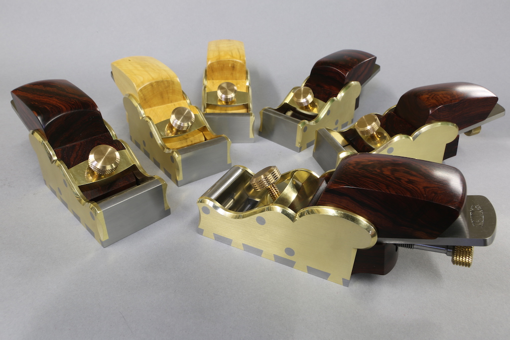
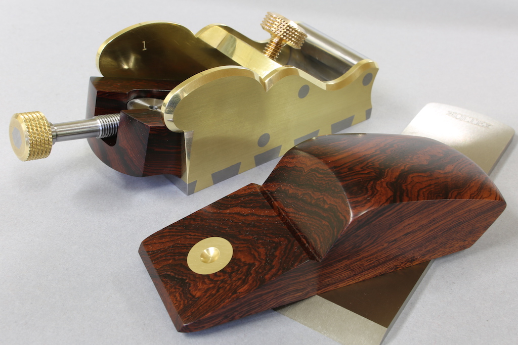
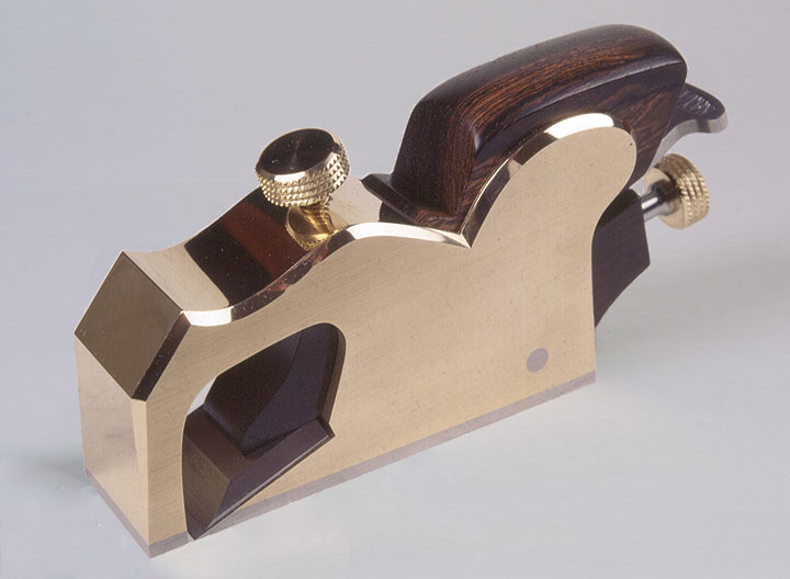
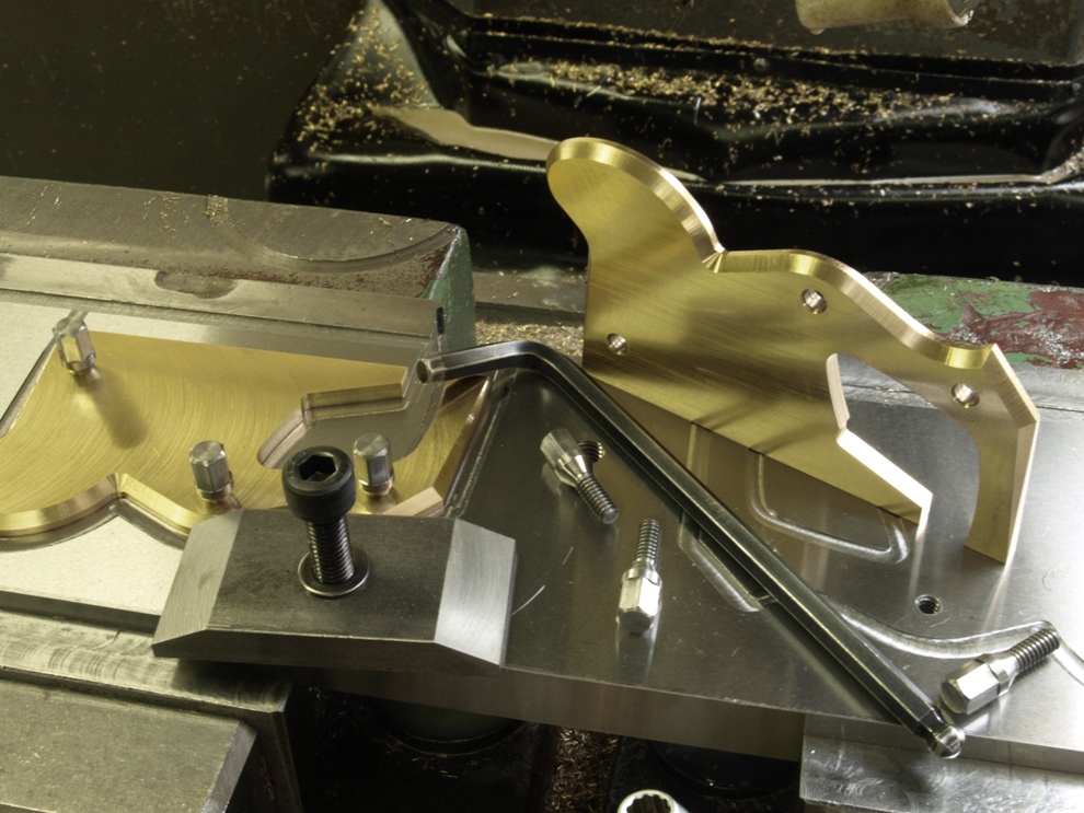
As I have said on my web page the No 984 panel plane is to be my last. This is the beginning of the promised blog. I have been a bit slow starting as I have been busy with stock sales and many enquiries. Thank you very much for all your nice comments – I am not actually retiring as most people I knew retired and died, I will keep up the coffin dodging and I have many other things to do. These No 984 planes will keep me going for about 3 months.

Holtey No 984 a

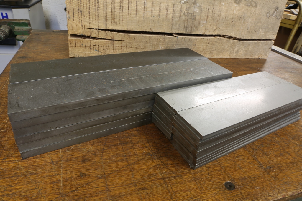
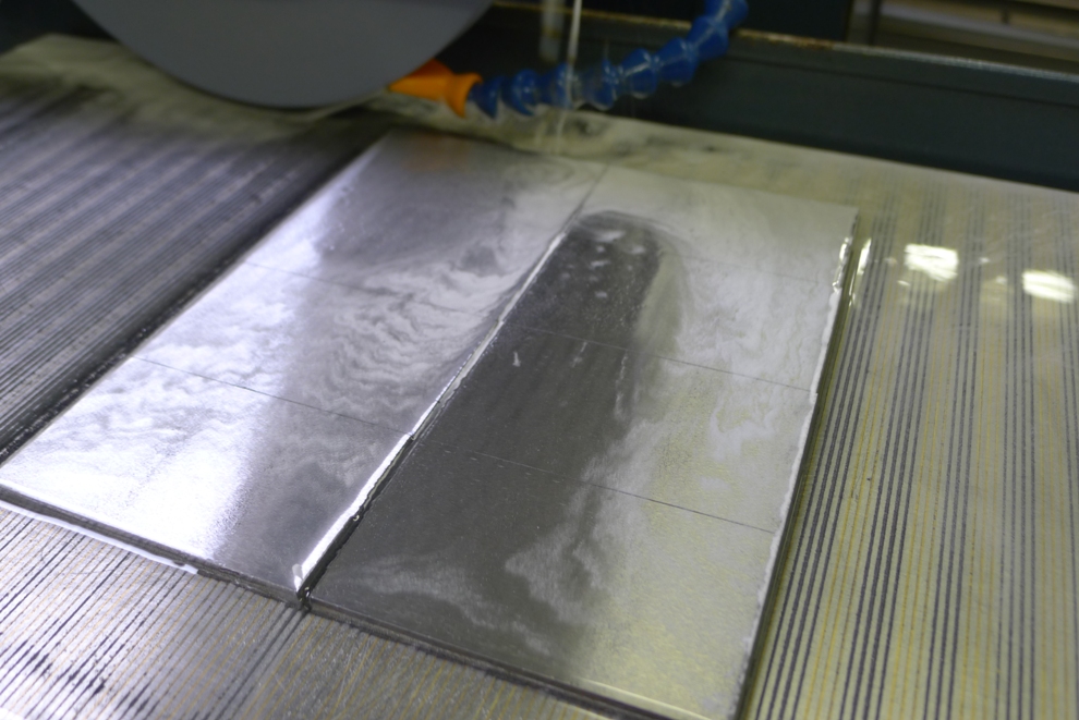
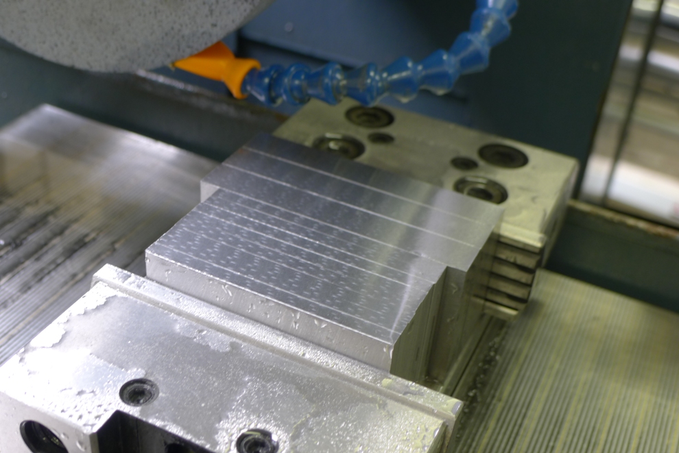
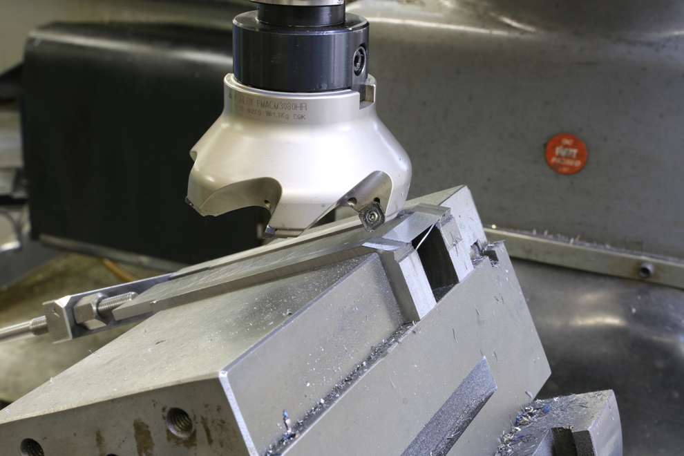
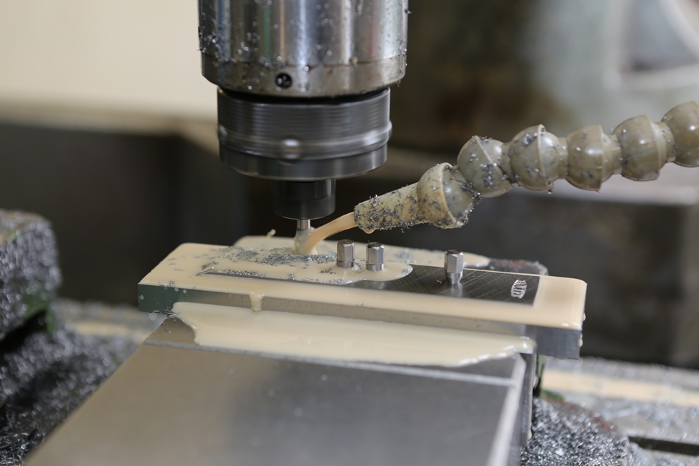
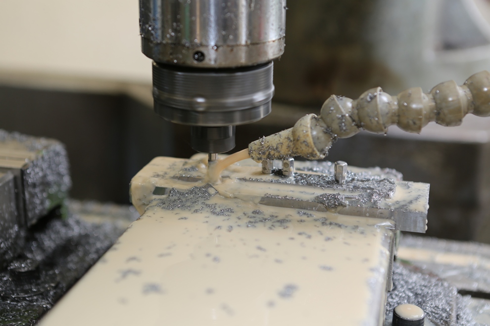
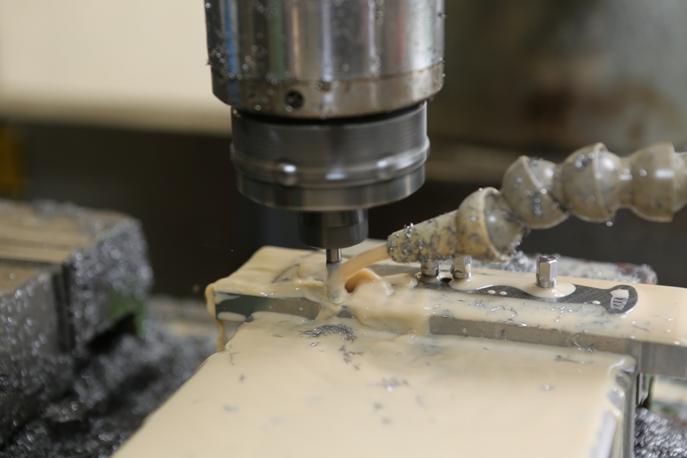
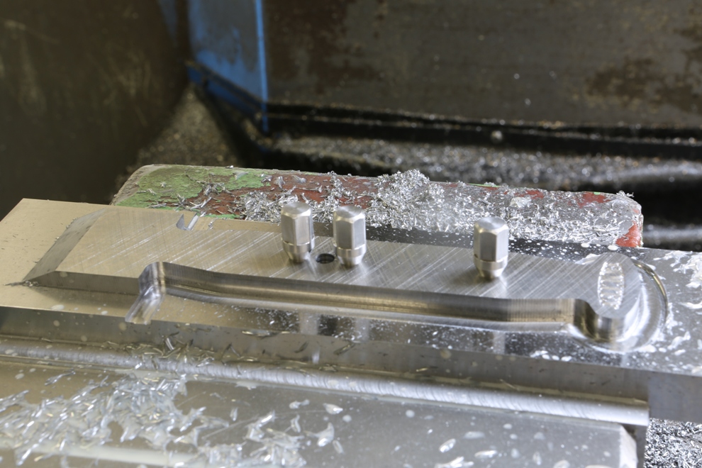
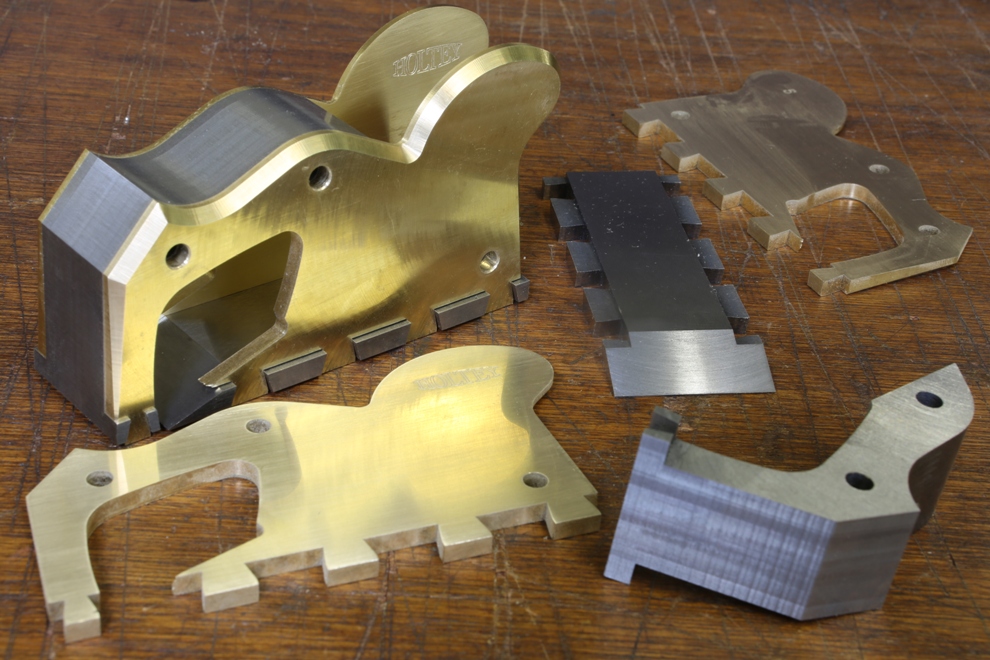
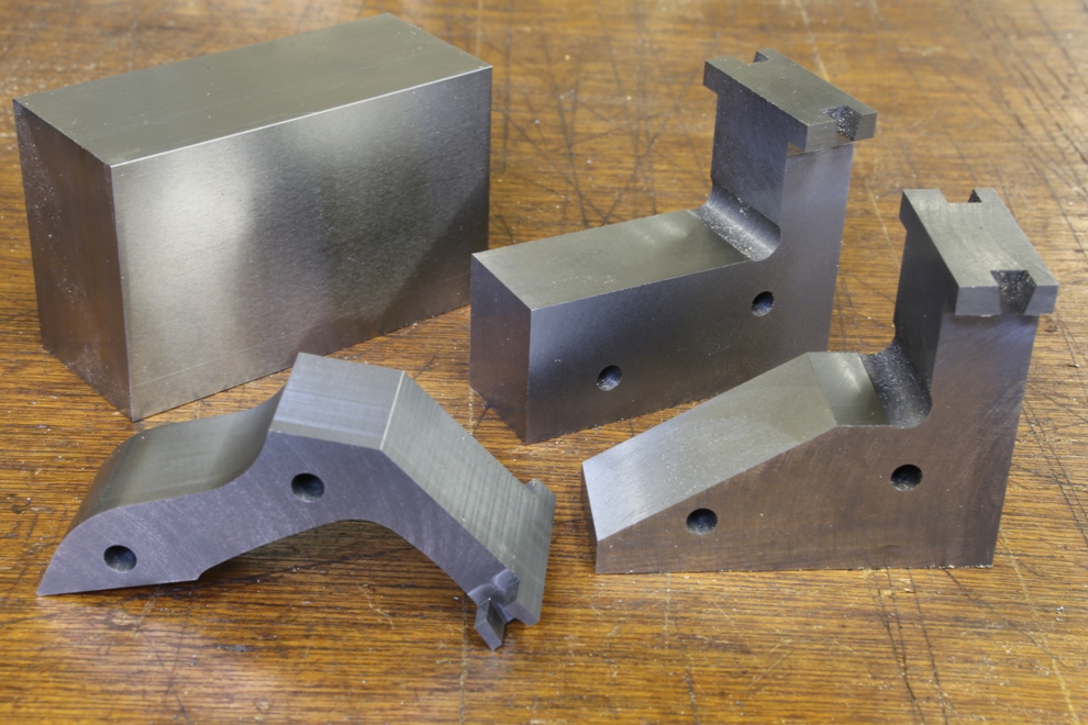
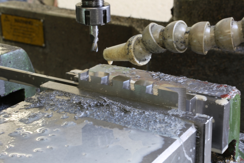
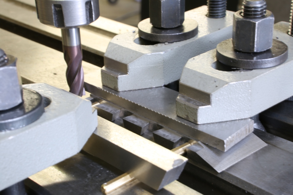
This is the 420 stainless steel that I am using for the bottoms and sides of the plane. The plan is to start knocking some weight off them. I am trying not to let the weight of the finished plane go over 3 kilos. All surfaces will be milled and ground. The steel that I have here is enough to make a limited batch of 12 planes.

Holtey No 984 b

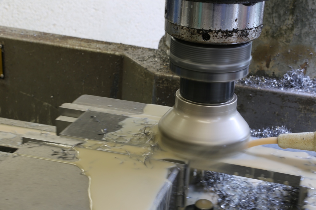
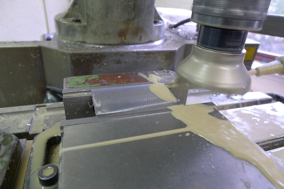
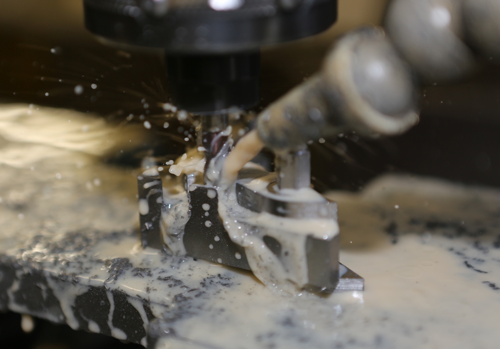
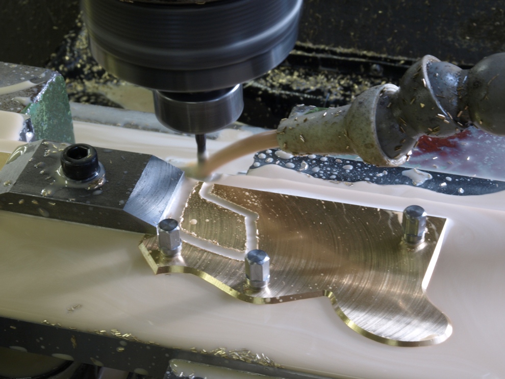
Here begins the slog, there is a lot of material to come away. This picture shows a bottom starting out 12 mm thick and it will end up just over 10 mm in the finished plane.

February 21, 2015

Window to my workshop 87

Filed under: A28 — Tags: , — admin @ 11:46 am

It has been a long time but the Chariot Plane is now finished. I have some No 983 planes to complete and then I am moving on to something new.

CI3A1405

CI3A1425

November 5, 2014

Window to my workshop 82

Filed under: A28,Chariot Plane,Window to my workshop — Tags: , , , , — admin @ 11:33 am

During the working of this A28 plane I have been neglecting this blog but now I am ready to update which I will do over the next few weeks.
 
 
Holtey A28 f
 
All the sections I use are cut out of stock material and brought down to size, by sawing and milling.
 
 
Holtey A28 g
 
As most of my working and setting out depends on a high degree of precision (which has never existed before) surface grinding in the early stages allows me to achieve my goals.
 
 
Holtey A28 h
 
This picture shows the edges being ground. This is also important to have a true pinch dimension. I need this for the dovetailing.
 
 
Holtey A28 b
 
Jigs and work holding fixtures are also all made to precision. After much preparation work to the brass, similar to the steel work as described. Then rivet positions are drilled and I am able to screw these sides with purpose made bolts to the fixture for profiling and chamfering.


Holtey A28 c
 
After routing out the profile then the chamfering is completed whilst the sides are still jigged.
 
 
Holtey A28 d
 
Just overall set up pictures.
 
 
Holtey A28 e


Holtey A28 a
 
Here are the some sides already milled and some pre-prepared waiting for profiling.
 

September 1, 2014

Window to my Workshop 81

Filed under: A28,Chariot Plane,Window to my workshop — Tags: , , , , — admin @ 2:52 pm

This Chariot is the last item in the series of low angle planes I have been making recently. I have only made a few of these planes and that was a long time ago in my early days of plane making. Then my side profiles were cut by hand and I made up a template which I would scribe round. Now that I CNC these the machine can’t see my template so I have had to re-draw it showing co-ordinates to write a programme from.

This line drawing by today’s standards might look a bit primitive but I have never had the leisure to learn to use a CAD. With a drawing showing contours I can write this in to my control unit. Drawing contours is more instinct than anything and I just know when it is right however long it takes (I would be ashamed to tell you how long these ones took).

Holtey Chariot Plane - Copy

May 13, 2014

Window to my workshop 78

Filed under: A27 Bullnose,Window to my workshop — Tags: , , — admin @ 12:09 pm

Blades for the Bullnose plane


Holtey Bullnose 9
 
Cutting the blade bevel


Holtey Bullnose 11
 
The blade is secured by its adjusting holes etc, in a purpose made holding block, for profile milling.


Holtey Bullnose 13
 
The milling is coming to an end of the first cut.
 
 
Holtey Bullnose 15
 
The finishing cut.
 
 
Holtey Bullnose 16
 
Profiling complete, with just the side bevels to be done. This is a quick summary of some of the blade work.
 
 
Holtey Bullnose 17
 
A picture of the main components ready for assembly. It has been a long time getting here. It is just like climbing a mountain – you keep seeing false summits.
 

April 30, 2014

window to my workshop 77

Filed under: A27 Bullnose,Window to my workshop — Tags: , , , — admin @ 10:53 am

Back working on the Bullnose after so much downtime with the grinding machine maintenance:


A27 Bullnose Holtey 1
 
 
A27 Bullnose Holtey 2
 
 
Pictures 1 – 4
This is the cast iron infill for the Bullnose. As you can see this is a complex shape so I will let the pictures speak for themselves. As with most things I design and make I go places that have never been visited, making these planes very unique.
 
 
A27 Bullnose Holtey 3
 
 
A27 Bullnose Holtey 4


A27 Bullnose Holtey 6
 

This shows the pin side of the dovetails being milled.
 

A27 Bullnose Holtey 5


Rebating the tops of the dovetail area, which provides a light stop and gives the dovetails a better form. Again this system is unique to my planes.

February 10, 2014

Window to my Workshop 76

Filed under: A27 Bullnose,Window to my workshop — Tags: , , , — admin @ 12:29 pm

A27 pic1
 
This is one of only six A27 Bullnose planes I made many years ago. This was made by casting as were the original Norris. There were one or two downsides to this method of production so for some time I have been contemplating making a fabricated version using traditional dovetails. Now that time has arrived. It will be a limited edition, and as you will have realised I am moving away from traditional infill planes so unlikely that I will make these again. This is the second plane in the set of three low angle planes I have been making for some of my customers – A27, A28 and A31.


A27 drawings

 
A quick line drawing of the proposed plane. This is being made with naval brass sides (CZ112) and malleable cast iron for the bottoms, fore-end and bridge sections. I will be using a traditional wooden wedge and the adjuster housing is also rosewood. To my knowledge a Bullnose plane has not been made since Norris’s time in the 1920s – when it cost 23/- (shillings). I shall have to charge a little more. I have also moved the goalposts in regards to quality and precision.
 
 
O
 
The sides being routed on the CNC mill. All the precision work holding tools and jigs I made myself before starting this. Every plane I make has individual jigs and work holding which are surface ground to a high precision. My tool room has been built up over many years and is, I believe, the only one of its kind. You will not find this standard of precision anywhere else.
 
 
O

 
The riveting holes, include a 60 degree chamfer, which provides the jig fixing and positive location.
 
 
O
 
The mouth being cut out last as a separate job as it needs an additional clamping to support the front end – which can be seen to the left hand side of the picture.
 
 
O
 
Here is the finished side except for the dovetailing. It includes its mirror partner completing the pair.
 
 
As usual to be continued when I next have an opportunity.

February 6, 2013

Window to my Workshop 66

I thought it about time I wrote some more in my blog. Looking back on my past entries I notice that there are some gaps which I intend filling here.


At the beginning of any project the metal is a good place to start (after design and drawings are done of course). In all my classic designs I use mild steel – I have tried it in several different forms; hot rolled (which is very good and has little stress in but comes with a lot of scale to deal with), BMS (which is nice and clean but has a lot of stress in it), sheet metal (which still has a difficult scale to deal with and some stress). Stainless steel would be my favourite choice, but not on the classic type of planes. I therefore choose mild steel as this is a nice ductile material once the stress problems have been dealt with. To relief the stress I have to cut it to manageable sizes and send it off for heat treatment. This picture shows the material in two stages – after heat treatment and some after surface grinding.


As you can see from the picture my grinding machine is a Jones and Shipman 1430. It was made in the ‘60s and it has been reconditioned by Andmar who are more ‘Jones and Shipman’ than the company themselves. It has been the main stay of my workshop since I purchased it 10 years ago as all my work including tool making passes through here. That is every jig and every piece of work holding (as well as plane components). It sets the standard for all my work.


This surface grinder uses a 24” x 12” Eclipse magnetic chuck which needs re-surfacing every 12 months. This can take up the best part of a day. The nice true surface is so good I just had to photograph it (sad isn’t it!).


My current project is A1 14 ½” Panel planes. I have documented this before (use this link http://www.toolworkshop.co.uk/blogarchive/) so I am just putting a few pictures to look at.


April 26, 2012

Window to my Workshop 63

Filed under: No 982 Smoothing plane,Window to my workshop — Tags: , , , , — admin @ 12:16 pm


These are the front bun chairs and once the blanks have been cut and trimmed up true to uniformed size the central fixing hole is drilled whilst still in the lathe. They are then tapped with an 8 x 1.25mm thread; this is for the bun screw.

The 3 x 6mm fixings are drilled on a manual milling machine using an indexing head as shown.


With the three index holes now drilled I only need a tool change to tap these three holes whilst still in the chuck.


Now that all my fixing holes are complete it is back to the lathe to form a small spigot where the bun in engaged.


The last job on the chairs now is to finish the bottoms to the 15 deg offset to the front buns. A small fixture has been made for this purpose. The chairs are mounted with the three bolts.


The chair is held in its fixture and secured on the saw for cutting


Whilst the chair is still attached to the fixture it is clamped onto the tilting milling vice for surfacing to the desired dimension.


September 7, 2011

Window to my workshop 54

The final part of the A6 construction.
 

Drilling and countersinking frogs for the rivets.
 

The bottom has been slotted out for mouth and drilling for the corresponding  frog rivets.
(more…)

« Newer PostsOlder Posts »

Powered by WordPress