From the Workshop

October 17, 2011

Window to my workshop 55

No 10 smoother/mitre

A very patient customer asked me to make a small mitre plane. He wanted a 11/4” wide blade to be bedded at 25 deg and bevel up with a short body. No adjuster was required.

I would classify this plane as a smoother/mitre. The small mitre plane has always seemed to be surprisingly scarce for its usefulness. Having got my simple sketch approved the first batch is now well on the way (the sketch can be seen on the website here http://www.holteyplanes.com/).

It is a combined stainless steel bottom with naval brass dovetailed sides and brass lever cap and thumb screw. The blade is in my A2 original specification and has a top sneck. The length of the plane is 43/4“.

Despite its apparent austerity there will be no lacking in specification and quality. The designation will be No.10. Delivery will be end of November 2011.

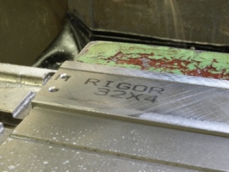
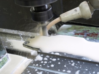
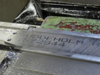
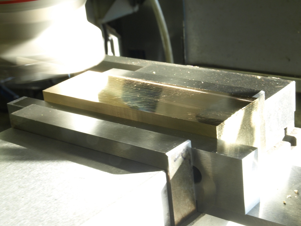
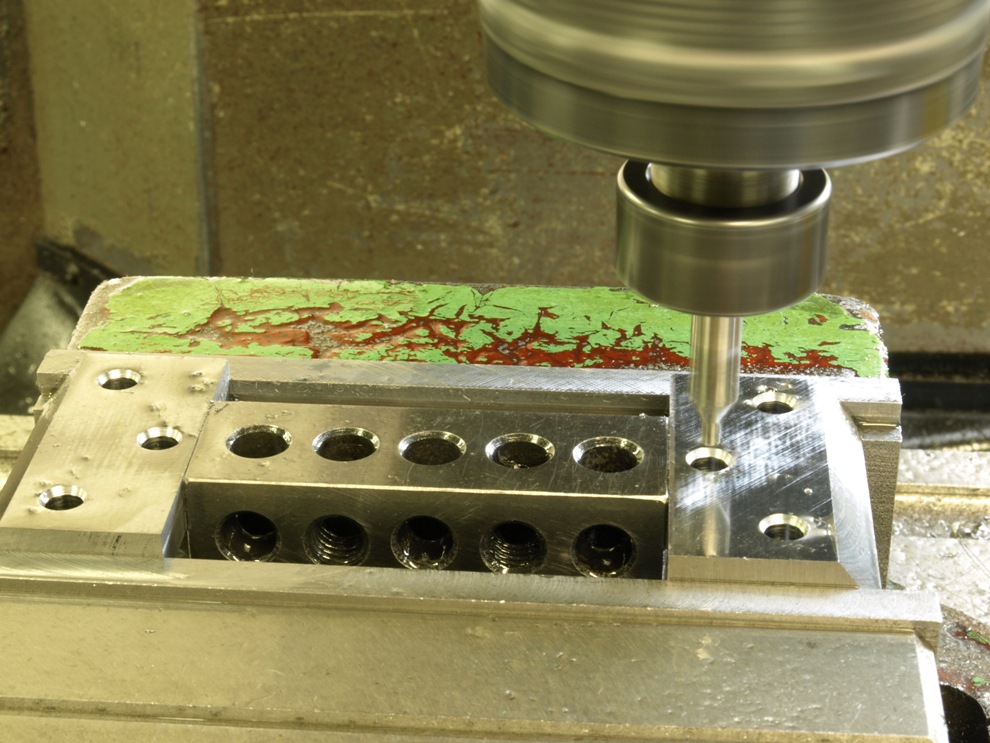
What better place to start than the blades.  Here are the A2 blanks being drilled and shaped.  These are now away being heat treated (the only work to be done out of house).


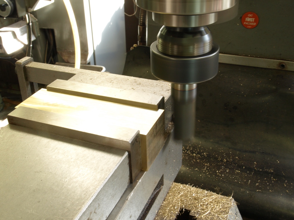
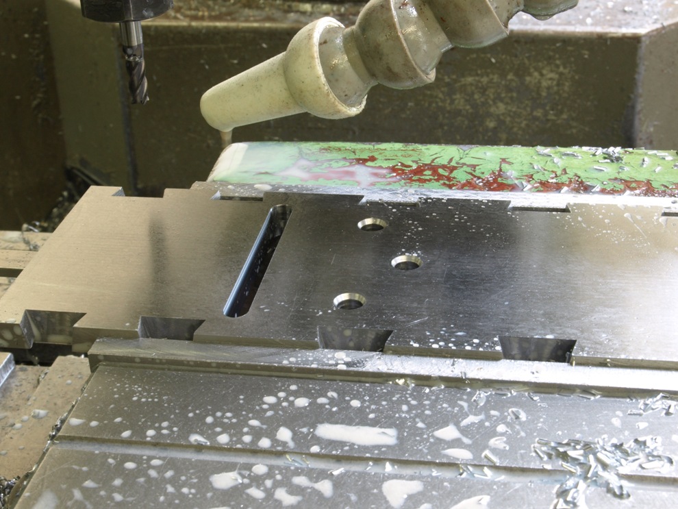
Brass sides have been cut from sheet and trued up into rectangular blanks. 
(more…)
September 7, 2011

Window to my workshop 54

The final part of the A6 construction.
 

Drilling and countersinking frogs for the rivets.
 

The bottom has been slotted out for mouth and drilling for the corresponding  frog rivets.
(more…)

November 5, 2009

Window to my workshop 28

Spiers Style Shoulder plane -4

Apologies for the 4 week gap in postings for those of you who have been following my blog.  I have been a bit busy with visitors (though always welcome it does tend to put me behind a bit), and the new project (transitional plane) keeps on snapping at me;  it is coming along quite well if a bit piecemeal.

 As I mentioned in the last posting that I had mislaid some pictures so here I am going to replace them with some from an A7 Norris type shoulder plane as they are very close in construction.

40 Spiers style shoulder plane

The front infill of an adjustable shoulder plane is probably the most complex infill of all my planes; especially as they are part of the adjuster design.  This infill is integral with the bridge and the clamping screw bush.  The clamping screw bush (which is illustrated in a previous posting) is screwed through the bridge. It also has a shoulder which secures the front part of the infill by clamping down on to a counterbore recess in the wood. This arrangement eliminates the need for a rivet here.  

All the boring, counterboring and tapping is done in a set sequence whilst everything is in situ.  After this process the whole plane is disassembled for further work.  This includes the fixing of the infill to the bridge with the brass bush.  With the fixing secure and complete the brass bush on the underside of the bridge can then be flushed off.  By offering the filling back into position in the plane I can scribe the contour lines from the plane sides for reference for the shaping of the horn detail around the brass bush.  


41 Spiers style shoulder plane

Here the rear end of the shoulder plane is polished before the blade bed is fitted, otherwise it would be inaccessible.  This is typical of the importance of getting the sequence right throughout the whole project.

(more…)

October 4, 2009

Window to my Workshop 27

Spiers Style Shoulder plane - 3


I seem to have misplaced a few pictures along the way here but the blog is only intended as a glimpse of what goes on.


28 Spiers style shoulder plane

At this stage with the plane temporarily assembled I drill through the horn and the bridge with a pilot drill.
(more…)

October 3, 2009

Window to my Workshop 26

Spiers Style Shoulder plane – 2


18 Spiers Style Shoulder plane

Difficult to define a name for this component; It certainly is a bush and it is threaded into the plane’s bridge which will also hold down one end of the front infill through the horn.  This component also has an internal thread for the thumb screw that clamps the wedge.  The picture shows a temporary screw driver slot being cut which will be removed after assembly.

  (more…)

Powered by WordPress