From the Workshop

June 17, 2019

Possible new project

Filed under: New Projects — Tags: , , , — admin @ 11:46 am

Unable to sleep last night as often happens, memories were going round my head. I have been asked by violin makers if I would make a set of finger planes. I have said yes several times, but it has just gone in the pile of promises. It is interesting to know if there is enough interest in these planes. The one photographed here would serve as a template, allowing for design adjustments for size. It would be my idea to start small and work my way up the scale over a period of time to allow for people to recover from the price. There are plenty of these planes out there but I haven’t seen any quality ones. This ESE captured my attention.

20190617_095735

February 23, 2019

Workshop blog 12 – No 985

The last side of the No 985 plane. The fixture screws (custom made of course) are also going to be used in the fabrication of the plane. They will be bedded in a locking compound.

I have flitted backwards and forwards between this system and the in-situ riveting – they both have their plus points. Same quantity of work with either system. But working with this system puts less stress in the construction.

As you can see from these jig screws they have a precision shank for true alignment.

CI3A5171

February 13, 2019

Workshop Blog 8 addition

Filed under: Discussion,Window to my workshop — Tags: , , , — admin @ 2:57 pm

I couldn’t find this picture earlier on, but it has now appeared

G_A_adjuster_assembly_v02 patch 3

This is one of the best adjuster I have ever made, and I hope to revisit this but it is only suitable for a bevel down plane

Workshop blog 8 – No 985

Filed under: No 985,Window to my workshop — Tags: , , , — admin @ 10:48 am

I still keep revisiting the drawing board making final adjustments to my new plane the No 985 – seems to go on forever. Whilst I have been doing this I have been making comparisons between non-adjuster planes and adjuster planes and I am working on the basis that having an adjuster does double the price. I will try to explain the difference and why the work compounds.

Since designing my own planes I have moved on a long way from the earlier Norris examples. The Norris planes with their adjusters did tend to be a bit basic, like most planes of this time, almost bordering on primitive. You could literally recess the infill and drop the adjuster straight in, securing with two wood screws.

I will explain with an example of where a lot of the work goes, which doesn’t appear to have much to do with the actual adjuster. My adjuster designs are truly integrated into the plane, I don’t just pop an adjuster in as an extra!

CI3A2619

The photo below shows the swivel which is balled so it matches any irregularities whilst connecting with the blade. This is, like most of my design elements, my own innovation.

CI3A2626

As you can see the lever cap (from my No 984 plane which is blogged here:http://www.holteyplanes.com/blog/category/no-984/, showing the machine working) is stepped/recessed so that it will carry a swivel. This is necessary with adjuster planes as the swivel shoe will bridge the adjuster holes in the blade. From my research it appears that I am probably the first pioneer to drop the chip breaker on bevel down planes. The first plane I made like this was the 11-s (see photo)

11s ebony

As the 11s has no adjuster drillings the lever cap was quite straight forward and less work. When I made the No 982 I was able to avoid the holes in the blade with the lever cap placement but it put some limitations on the design.

IMG_2598

This is an example of the adjuster recessing in the No 983.

CI3A2712

This is the bottom for the No 984 showing the adjuster recess.

In summary: to add an adjuster, both adjuster and plane have to be truly integrated. Of course the adjuster has to be made as well.

February 5, 2019

Workshop blog 7 – No 985

Filed under: No 985,Window to my workshop — Tags: , , , — admin @ 10:44 am

I have spent a long time on my drawing board this year working on a new design – designated No 985 which will be part of my range of non-infill planes, which I very much prefer. This smoother is a non-adjuster type plane which means a reduction in work as the adjuster is a big item – both to make and accommodate, which will show in the price. Some people prefer a non-adjuster plane and I have not made this on a full handled plane before.

This plane is to be made from 416 stainless steel which is expensive and flat sections cannot be sourced in the UK. My experience with this alloy is that it is the best for my purposes. It is also preferred for making rifle barrels. It is very nice for working with and has a lovely texture to it. And I can stick it on a magnetic chuck for surface grinding.

Whilst waiting for the stainless to arrive I have made a start on the handles.

Holtey No 985 smoother plane

This is an area in which feedback would be greatly appreciated. Since I am making a smoothing plane my objective is to keep it as short as possible. A lot of the older planes were 7 1/2″ long which makes sense for finishing purposes. However, these planes were usually handleless, which can be uncomfortable to use. Once you introduce a handle it is going to increase the length. As this is a non-infill plane I will be using a round bun, which also needs a little bit of extra room. I would like to make the handles short for use with three fingers plus the index finger resting on the side of the blade. What I want feedback on is would you prefer a taller handle so you can use four fingers which will make the plane longer, or do you prefer three fingers and a shorter plane?

For those who have experienced my No 98 they will have noticed how comfortable the handle is as it has plenty of room for four fingers
- http://holteyplanes.com/. However, it is better to have the plane shorter if you are going to use it for smoothing/finishing.

If I use the taller handle the plane will be 8 3/4″ long or 8″ with the shorter handle.

A lot of modern smoothing planes seem to be about 9 1/2″ long which is neither a smoother or a panel plane – needs redefining.

Holtey No 985 handle templates

My handles are all hand made and I make several templates to find the one I am happy with.

December 14, 2018

New Workshop 5

Filed under: No 98 plane,Window to my workshop — Tags: , , , — admin @ 11:27 am

I have decided to put my blade chamfering onto the No 98 blade, it does set off a low angle plane – ergonomic and aesthetically. It is a lot of work, especially finding 30 deg chamfering tools (a 45 deg just doesn’t look right). The polishing is very time consuming. I have to do the polishing before I send them off to heat treatment, then I only need to buff the edges and surface grind when they come back.

No 98 blade chamfer

July 6, 2017

Window to my Workshop 115

Filed under: Drawings,No 983 block plane — Tags: , , , — admin @ 9:04 am

In conversations over the years I have always been praised for my (primitive) drawings as CAD is the way now. (See the dinsaour card on my Facebook page – thank you David) I have never had to time to learn CAD. The hardest thing was to learn an early Heidenhain control unit for my mill. I am just starting a new batch (yes, I know I am supposed to be retiring :-) ) of these No 983 planes, mainly because I sold the last one which was mine, I am going to use this opportunity to explain some of the workings in more depth. Maybe because I am getting older the work seems to expand but I have never allowed economic restraints to get in the way.

Going back through some of my drawings, which are very untidy, I decided to post some up. Starting with this side layout of the No 983 – warts and all. This is how I work and then I have to convert it into a suitable dialogue for my Heidenhain. Luckily I am the only person who has to understand this.

No 983 outline 1

November 30, 2015

Window to my workshop No 99

Filed under: No 984 — Tags: , , — admin @ 10:52 am

LEVER CAP

As with many of my components these are fabricated from solid bar. The three pictures shown below are starting from a raw bar, removing the excess and shaping then the finished product.


CI3A2423
 
CI3A2495
 
CI3A2511


This has probably been one of the most labour intensive of all the parts. Now that they are done, with the exception of polishing (which is no mean feat), I am very happy to move on to the thumb wheel and pressure pad.
 
Update: A modification has been made for ergonomic purposes. An additional chamfer has been added in case there is any contact with fingers or knuckles.
 
CI3A2522
 
CI3A2521

November 2, 2015

Window to my workshop 98

Filed under: No 984 — Tags: , , , — admin @ 5:41 pm

The pictures don’t do justice to the time spent on every little operation. Although I have taken many photographs along the way I don’t have time to document every little stage. The effort for every detail can seem a bit over the top, and I make little revisions all the time – the overall design will still be as the posted line drawing.

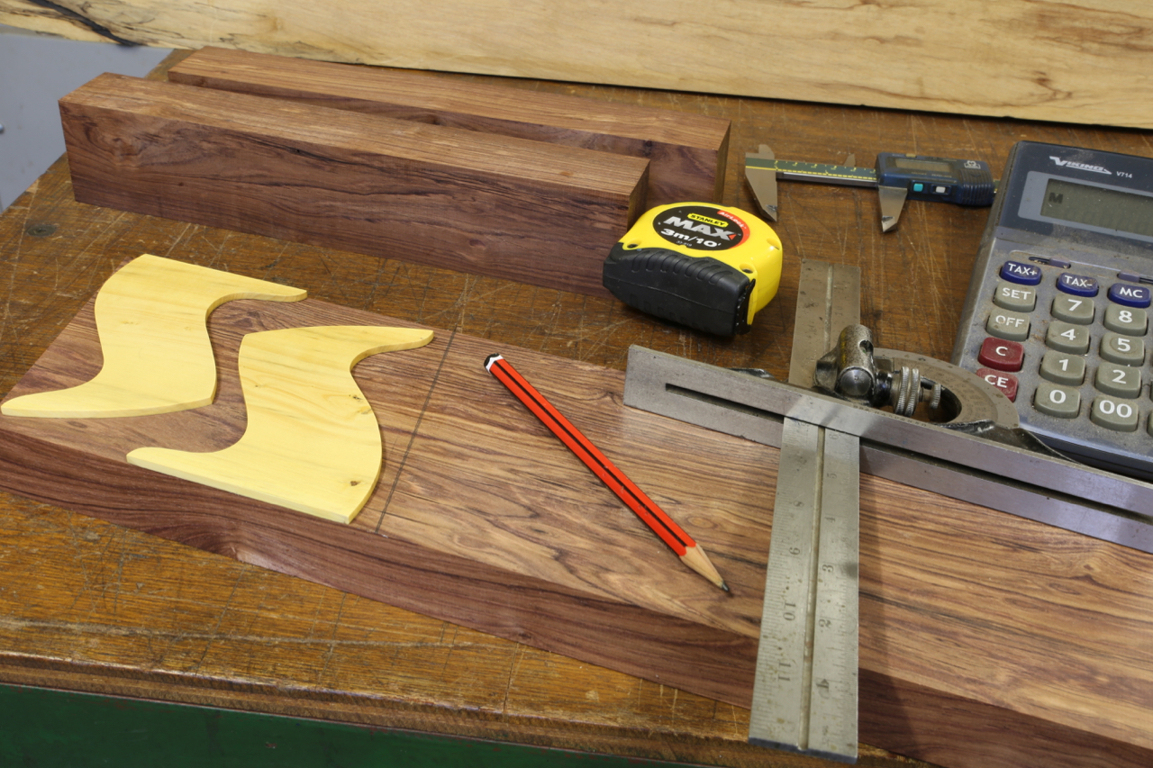
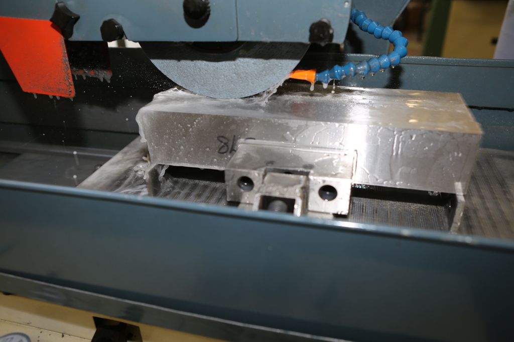
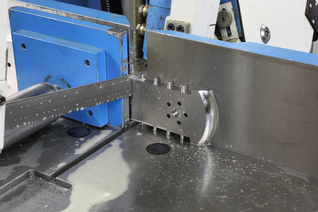
This is a nail biting moment, once I start cutting there is no going back. I can take hours double checking before I separate the toe from the the rest of the sole.


Holtey No 984 pic 7

 
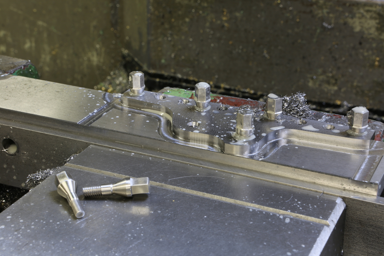
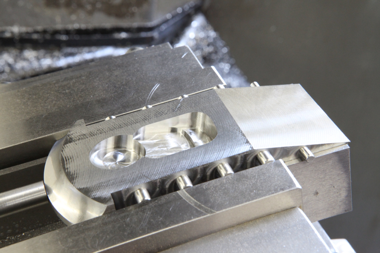
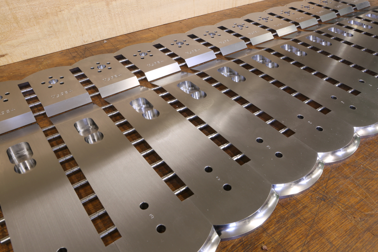
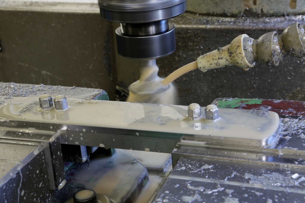
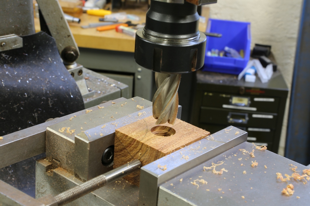
Here I am milling the blade bed. The rest of this operation hasn’t been photographed as I covered this in the No 983 blog and it is almost identical as are the adjuster recesses. You can see that the work holding vice jaws are purpose made just for this plane. This enables me to get a firm grip.
 

Holtey No 984 pic 8


Holtey No 984 pic 9

 
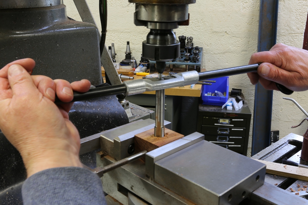
All my buns start off as a true square block. All drilling, tapping and recessing is carried out on the mill


Holtey No 984 pic 10


Holtey No 984 pic 11
 

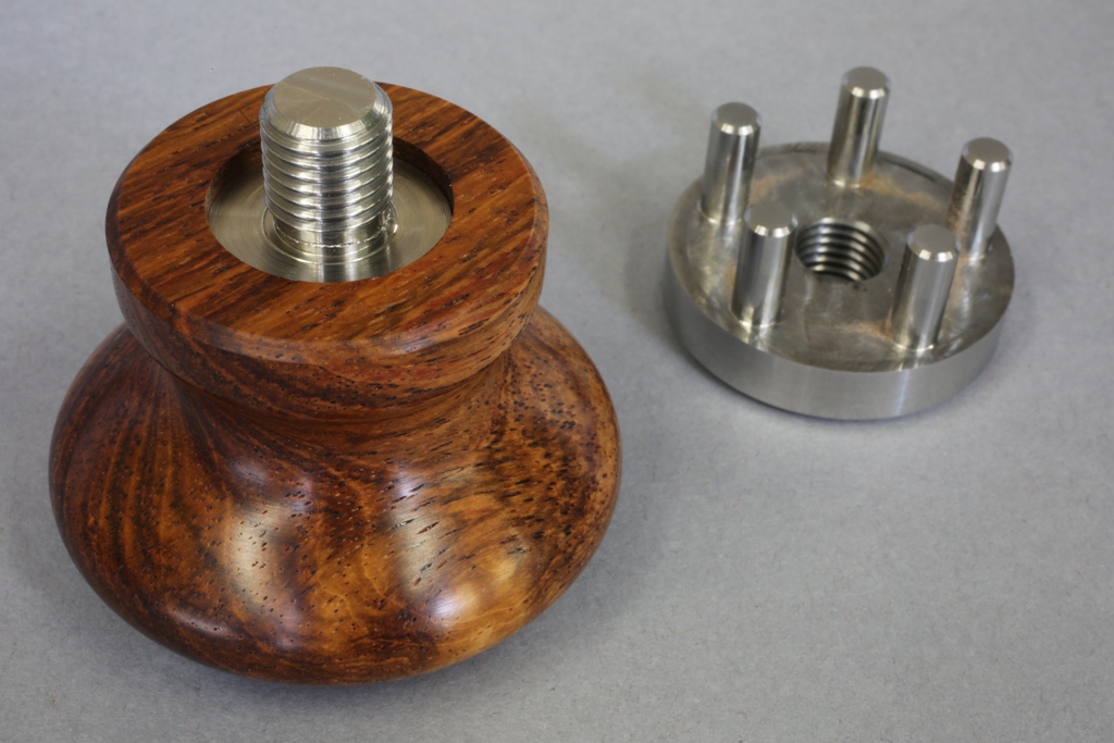
The bush shown here is to be epoxied into the front bun. You can use some imagination as to how I arrived here. The combined strength of the bush and its bun is considerable. Note there are two flats which make it impossible to remove the bush once the epoxy has cured.
 

Holtey No 984 pic 12

 
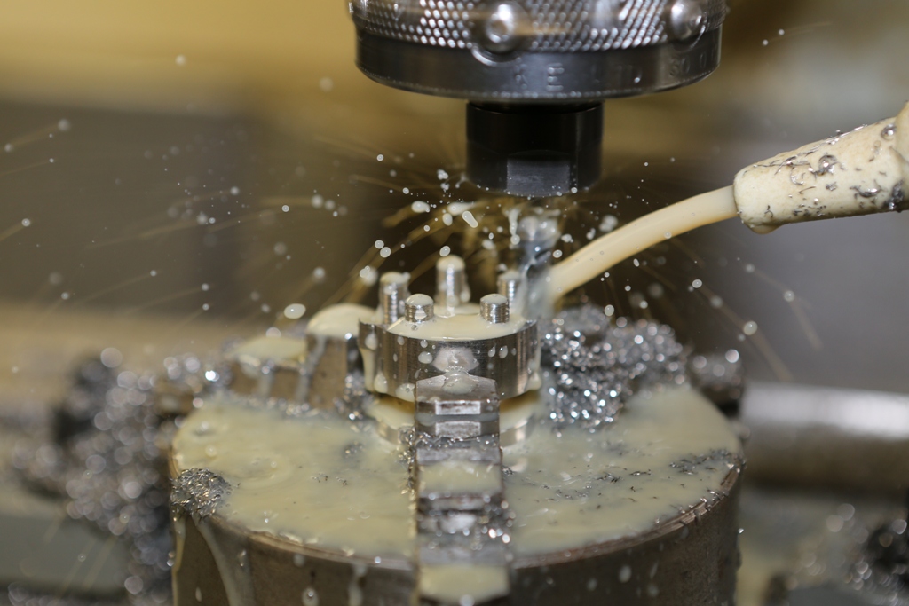
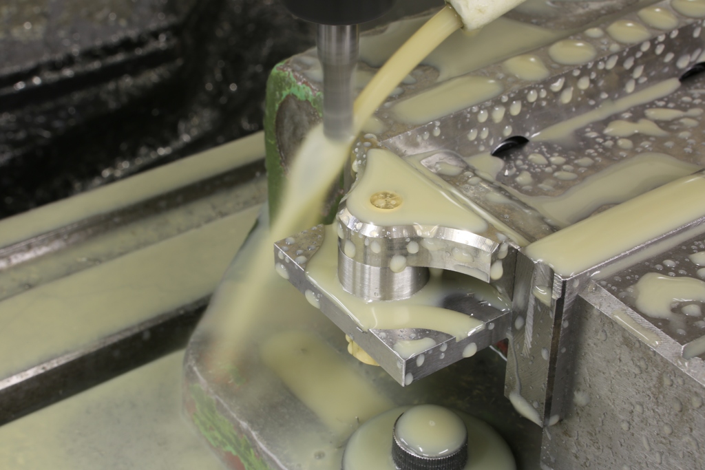
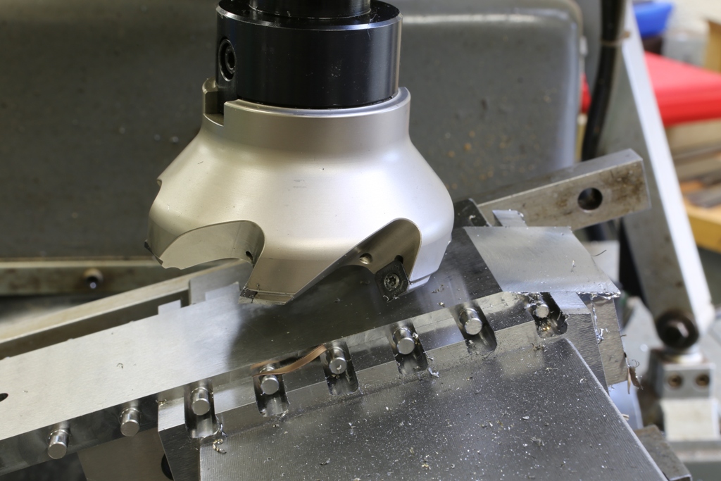
This is the milling operation for the five integral pins/rivets to the bun boss.
 
Holtey No 984 pic 13

 
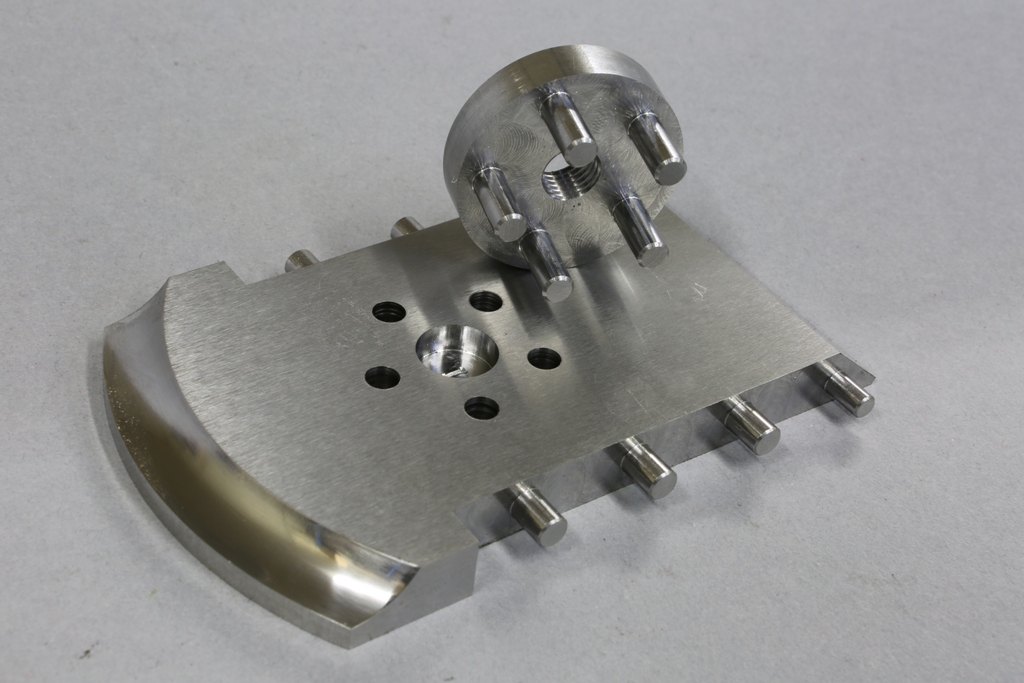
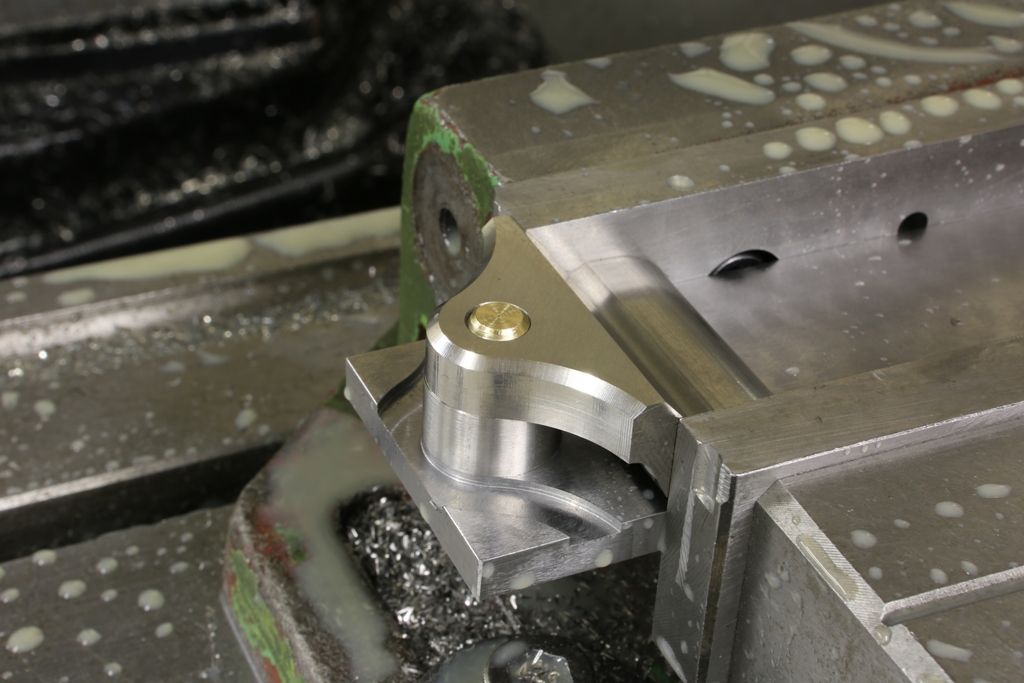
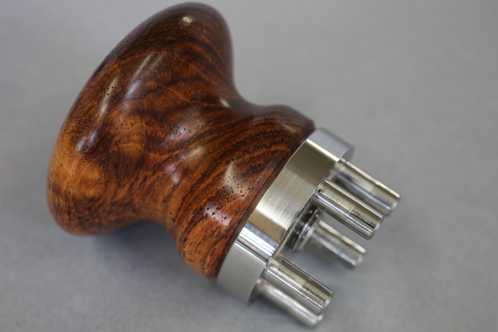
This is the finished boss for the front bun. I have chosen this method of fixing for its strength. I wasn’t happy about tapping blind holes. Who cares, it is not about cost :-) It is going to be the only one of its kind.

 
Holtey No 984 pic 14

 
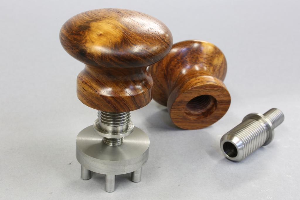
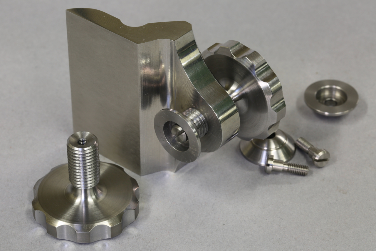
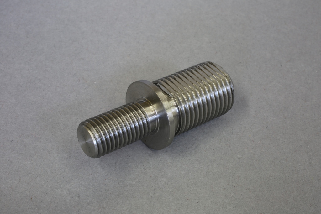
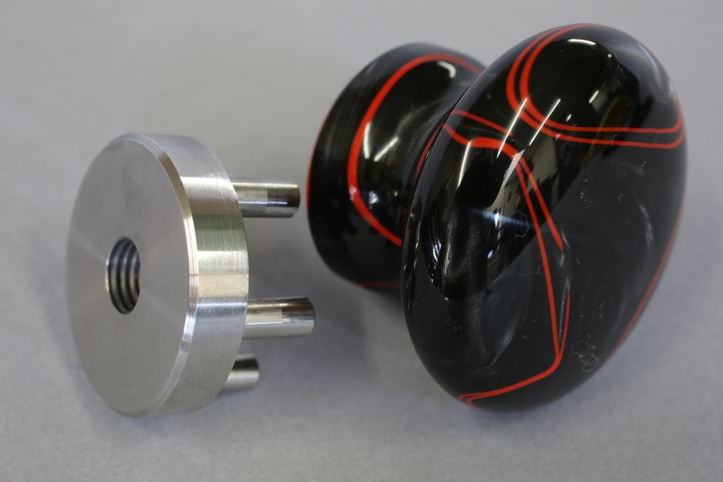
Illustrating the fitting of the bush to the bun and the threaded nose to fit the finished bun to its boss.
 

Holtey No 984 pic 15

 
Once this is complete, the bun can be removed and the boss is ready to rivet in place. Note that I used a V joint between the boss and the knob base. The knobs will leave my workshop perfect but the rotary position of the knob can have a tendency to migrate and wood can lose its concentricity over time. Also when the knob is removed and refitted the sharp edges can be bumped, thus losing the desired effect. The V joint will hide any of these unsightly dinks.
 

Holtey No 984 pic 16

 
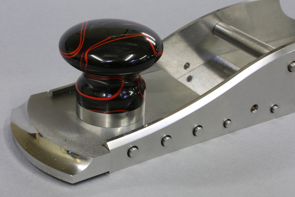
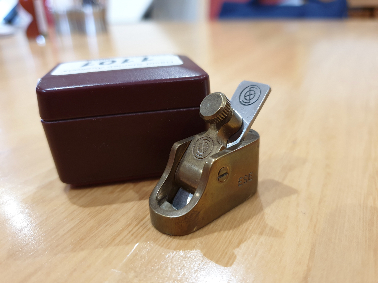
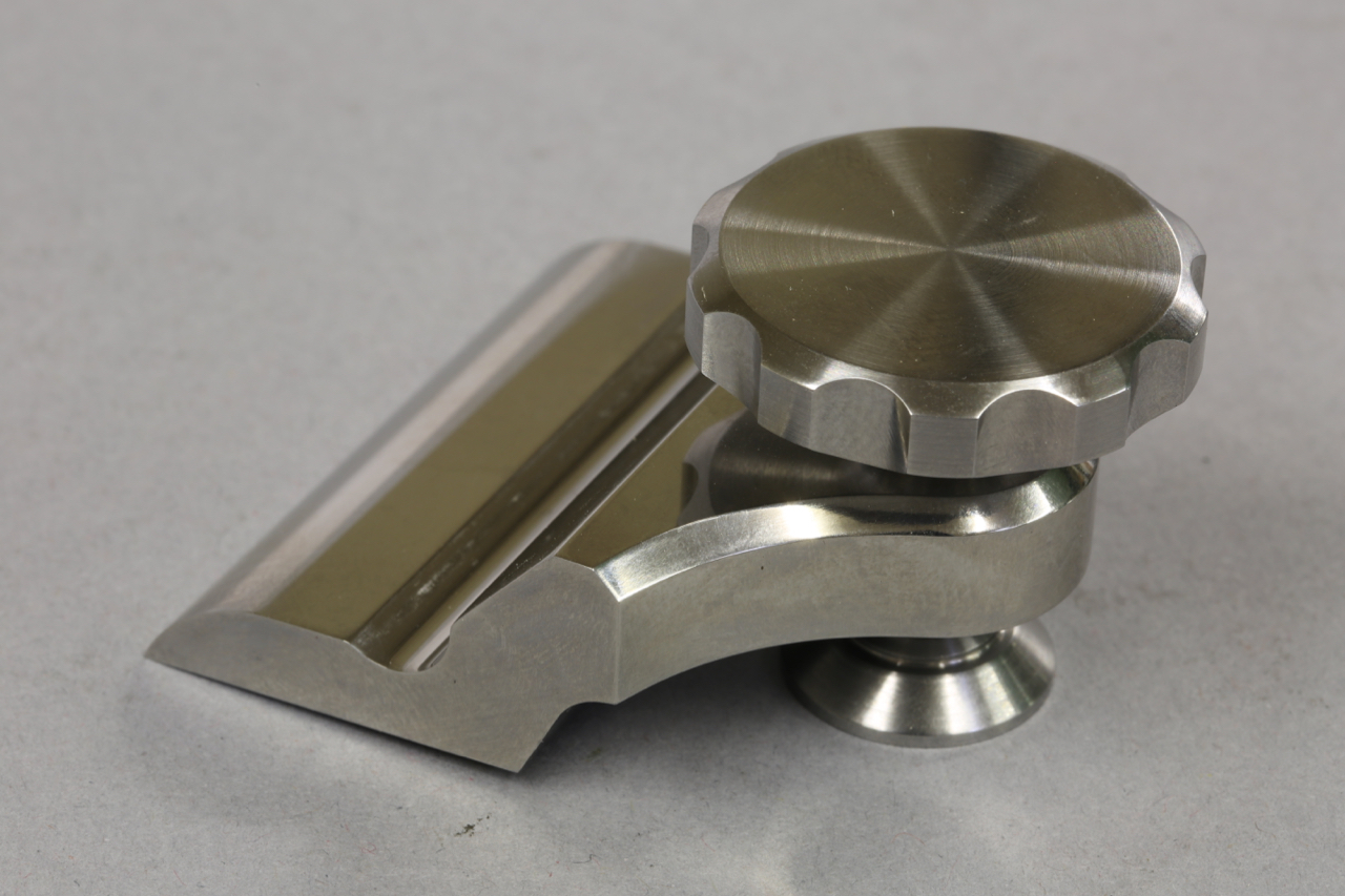
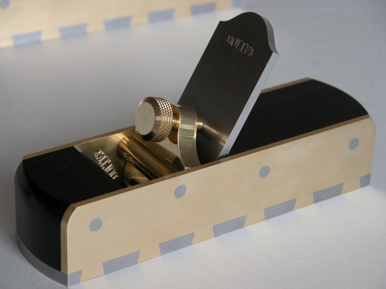
Temporarily assembled plane.


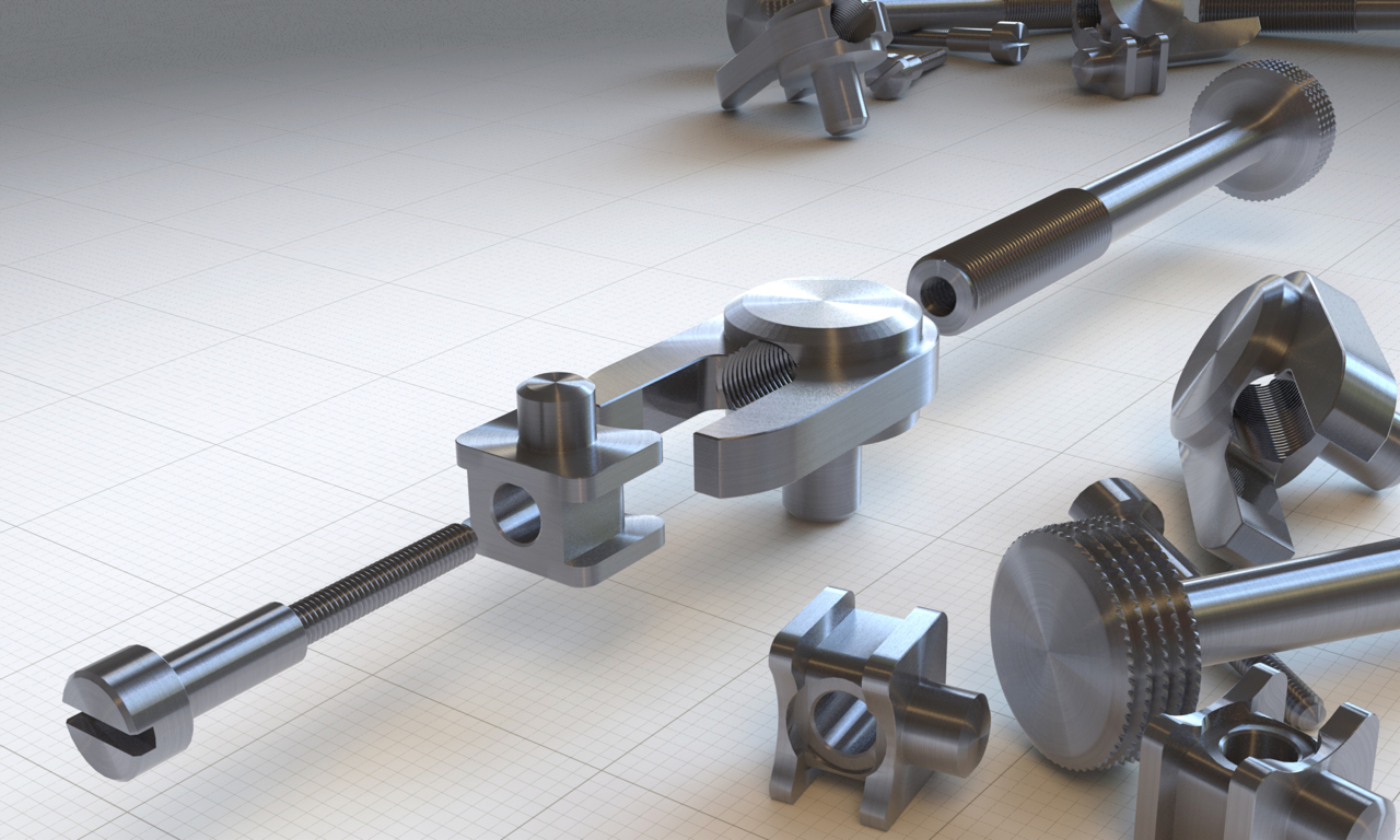
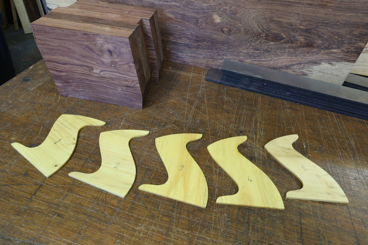
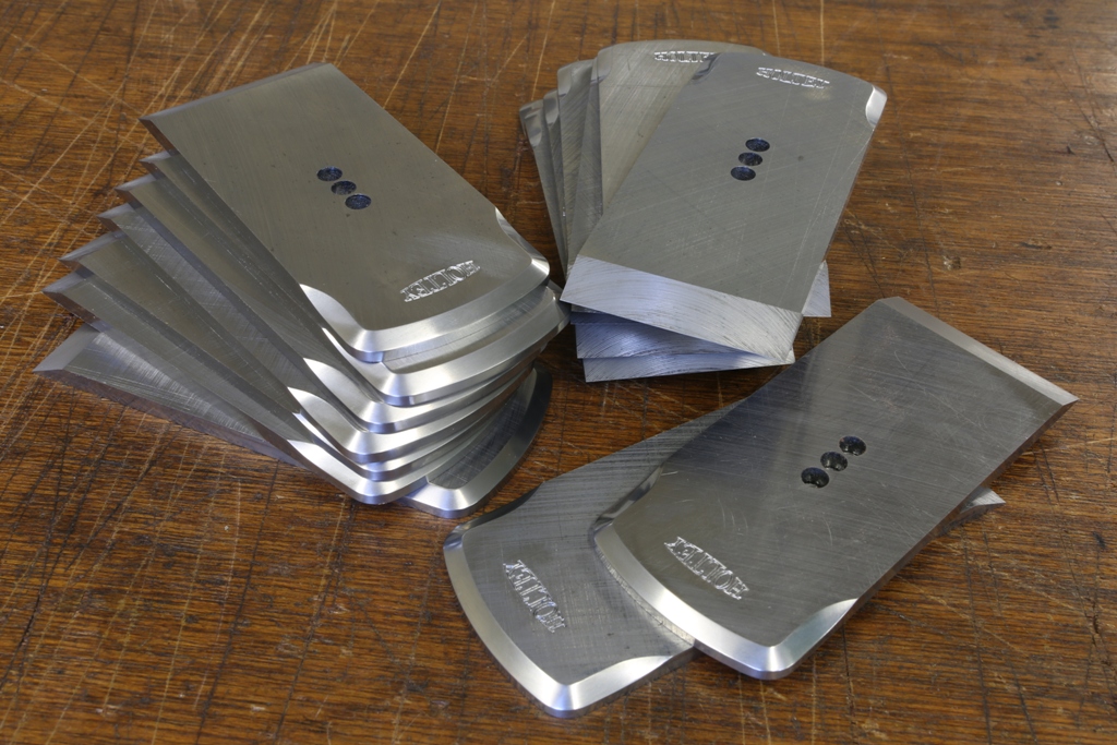
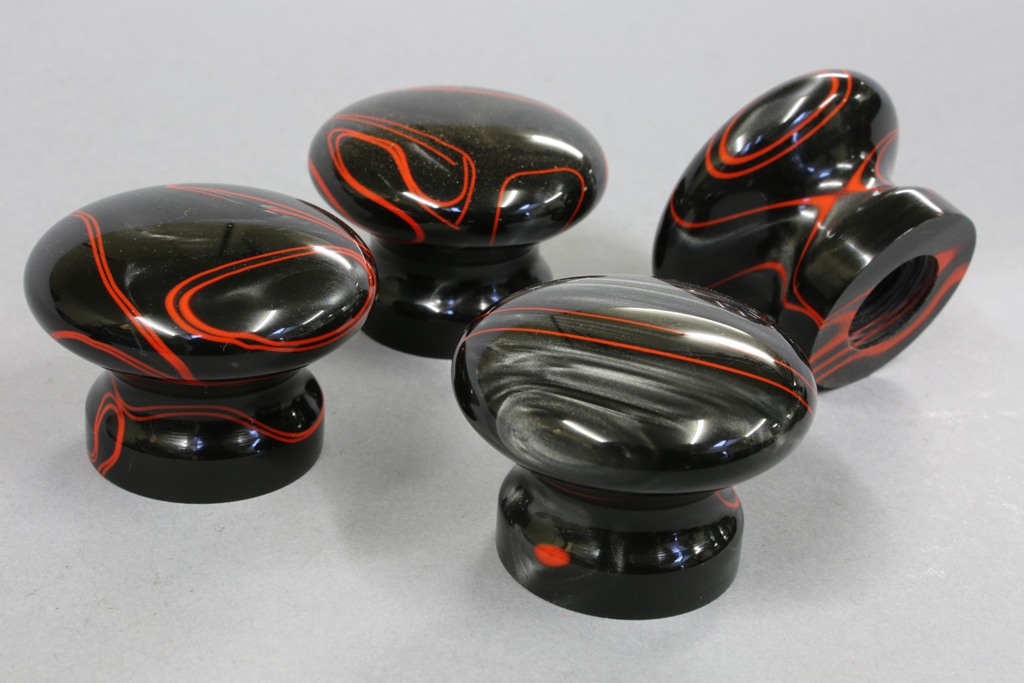
A general selection of knobs and parts.

 
Holtey No 984 pic 17


Holtey No 984 pic 18
 
Holtey No 984 pic 19


Still a long way to go, sorry to those who have a plane on order.


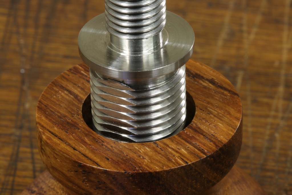
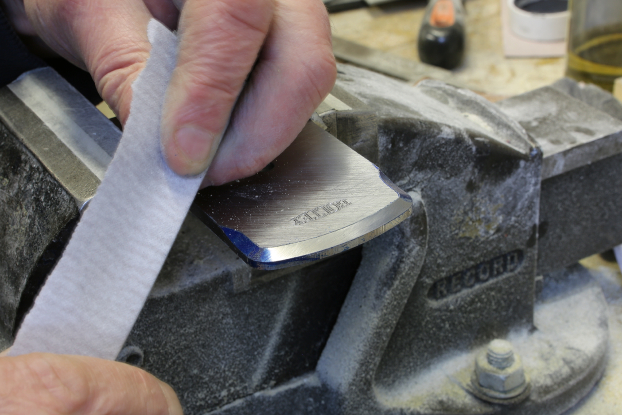
Thought this was worth a picture and mention. The bushing here had been cemented with epoxy and I had started it with a few threads and then I was distracted ………

I discovered how strong this system is when I came back the next day. I will keep this as a reminder.

No 984 cockup

July 6, 2015

Window to my Workshop 90

Filed under: No 984 — Tags: , , — admin @ 11:11 am

The surface grinder has been the busiest machine in my workshop for the past few years. All my sections, after size adjustments in the milling machine, are precisely ground all round. The same with all the tooling and work holding I make. This is necessary to get a good reference throughout all my work.

Holtey No 984 c

These are the bottoms being ground on their edges insuring that they are square and parallel. It is not often I use a flash but it is nice how everything has been frozen in time.

Holtey No 984 f

I have also been busy during this time with the blades. The blades are being profiled in ‘Siamese pairs’ for easier work holding. These have already been stamped with the HOLTEY logo in the fly press, I do this first as the edges close to the stamping area can become distorted.

Holtey No 984 g

After the blades are separated they need to have a bevel milled on and the chamfers polished before sending them away for heat treatment. The polishing to the chamfers is important as it would be very hard to do after the blades had been hardened. When the blades come back from the heat treatment I will be surface grinding them all round.

Older Posts »

Powered by WordPress