From the Workshop

June 10, 2014

Window to my Workshop 80

Filed under: A27 Bullnose,Window to my workshop — Tags: , , — admin @ 3:59 pm

The bullnose and shoulder plane blades must be the most work intensive. Once finished I celebrate with a photo!
 

Bullnose blades 2
 
 
Bullnose infills
 
Infill/adjuster housing/plane bed – whatever

Always a good feeling when nearing completion, although there is still a lot of fitting and finishing after they are separated.

May 14, 2014

Window to my Workshop 79

Filed under: A27 Bullnose,Window to my workshop — Tags: , — admin @ 10:53 am

Blades back from heat treatment. They have been vacuum hardened and triple tempered, followed by a two hour nitrogen soak. Note that there is no colouration to the blades, which means there were perfect conditions with no leakage.
 

Holtey bullnose blades
 

Now they ‘just’ need polishing and surface grinding.

May 13, 2014

Window to my workshop 78

Filed under: A27 Bullnose,Window to my workshop — Tags: , , — admin @ 12:09 pm

Blades for the Bullnose plane


Holtey Bullnose 9
 
Cutting the blade bevel


Holtey Bullnose 11
 
The blade is secured by its adjusting holes etc, in a purpose made holding block, for profile milling.


Holtey Bullnose 13
 
The milling is coming to an end of the first cut.
 
 
Holtey Bullnose 15
 
The finishing cut.
 
 
Holtey Bullnose 16
 
Profiling complete, with just the side bevels to be done. This is a quick summary of some of the blade work.
 
 
Holtey Bullnose 17
 
A picture of the main components ready for assembly. It has been a long time getting here. It is just like climbing a mountain – you keep seeing false summits.
 

April 30, 2014

window to my workshop 77

Filed under: A27 Bullnose,Window to my workshop — Tags: , , , — admin @ 10:53 am

Back working on the Bullnose after so much downtime with the grinding machine maintenance:


A27 Bullnose Holtey 1
 
 
A27 Bullnose Holtey 2
 
 
Pictures 1 – 4
This is the cast iron infill for the Bullnose. As you can see this is a complex shape so I will let the pictures speak for themselves. As with most things I design and make I go places that have never been visited, making these planes very unique.
 
 
A27 Bullnose Holtey 3
 
 
A27 Bullnose Holtey 4


A27 Bullnose Holtey 6
 

This shows the pin side of the dovetails being milled.
 

A27 Bullnose Holtey 5


Rebating the tops of the dovetail area, which provides a light stop and gives the dovetails a better form. Again this system is unique to my planes.

February 10, 2014

Window to my Workshop 76

Filed under: A27 Bullnose,Window to my workshop — Tags: , , , — admin @ 12:29 pm

A27 pic1
 
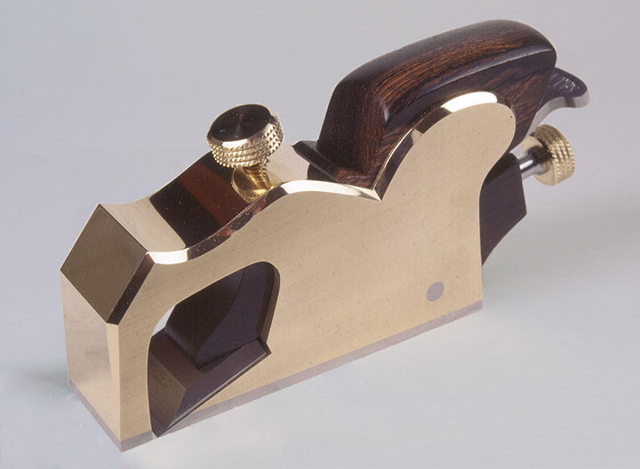
This is one of only six A27 Bullnose planes I made many years ago. This was made by casting as were the original Norris. There were one or two downsides to this method of production so for some time I have been contemplating making a fabricated version using traditional dovetails. Now that time has arrived. It will be a limited edition, and as you will have realised I am moving away from traditional infill planes so unlikely that I will make these again. This is the second plane in the set of three low angle planes I have been making for some of my customers – A27, A28 and A31.


A27 drawings

 
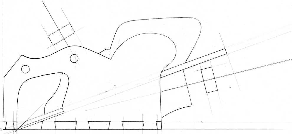
A quick line drawing of the proposed plane. This is being made with naval brass sides (CZ112) and malleable cast iron for the bottoms, fore-end and bridge sections. I will be using a traditional wooden wedge and the adjuster housing is also rosewood. To my knowledge a Bullnose plane has not been made since Norris’s time in the 1920s – when it cost 23/- (shillings). I shall have to charge a little more. I have also moved the goalposts in regards to quality and precision.
 
 
O
 
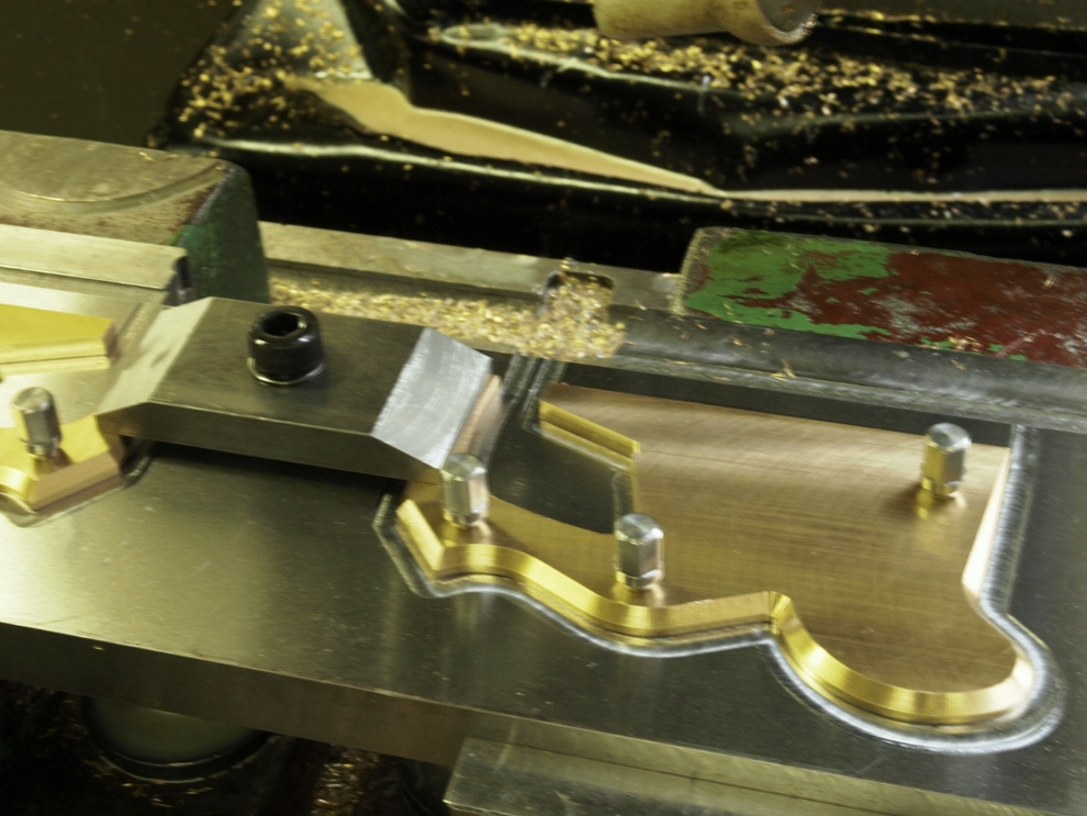
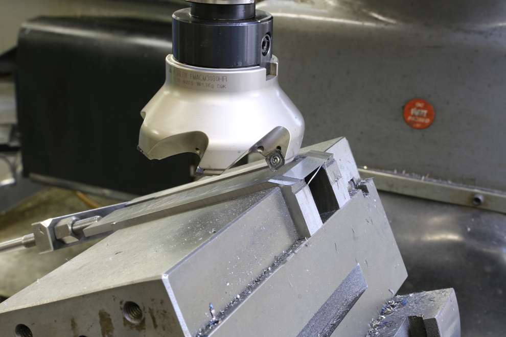
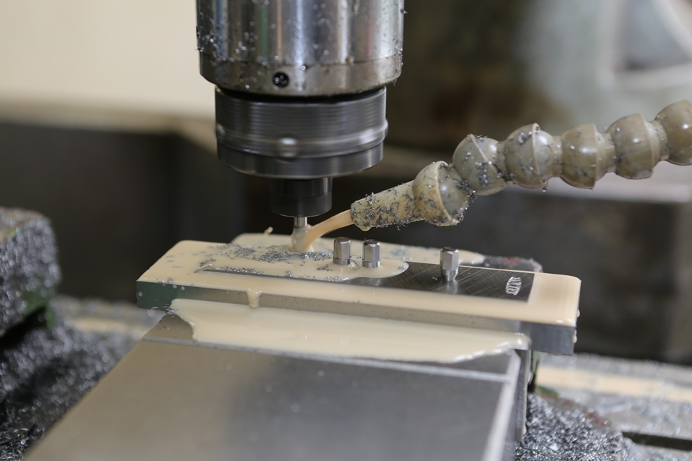
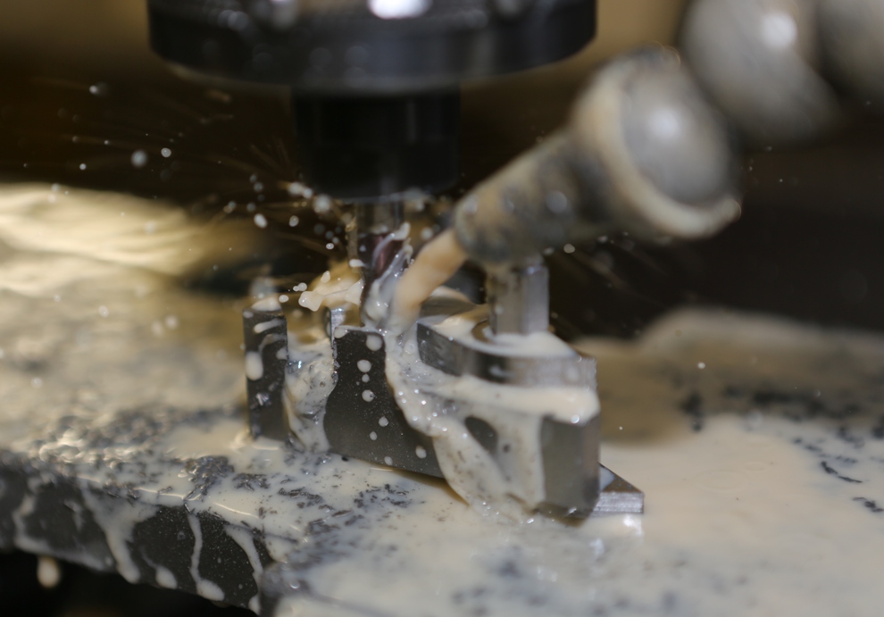
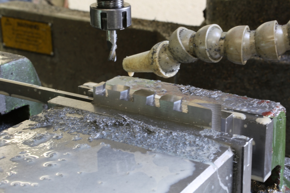
The sides being routed on the CNC mill. All the precision work holding tools and jigs I made myself before starting this. Every plane I make has individual jigs and work holding which are surface ground to a high precision. My tool room has been built up over many years and is, I believe, the only one of its kind. You will not find this standard of precision anywhere else.
 
 
O

 
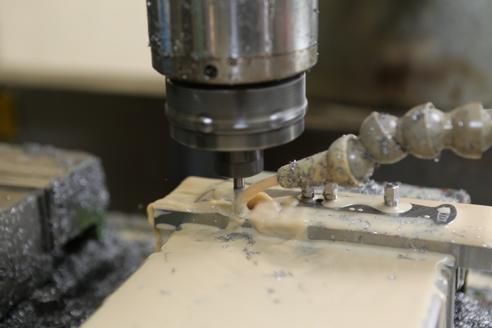
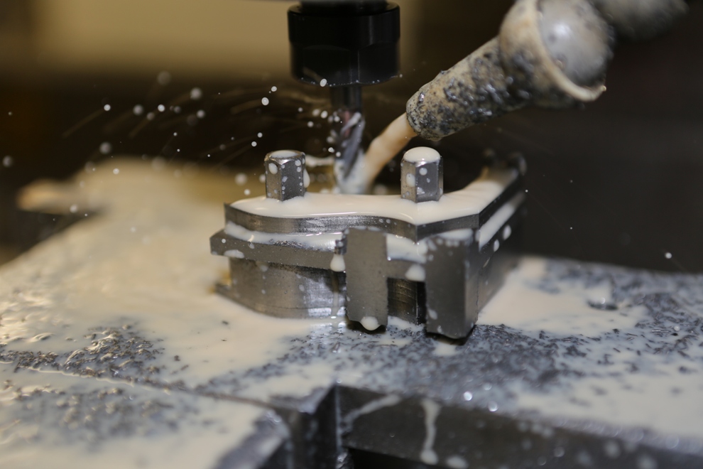
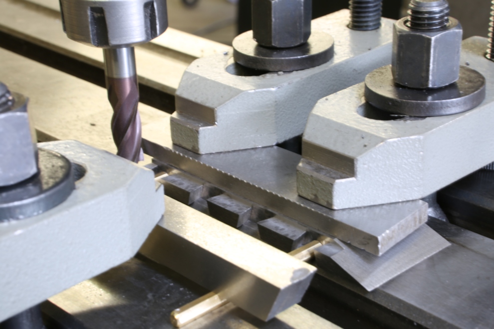
The riveting holes, include a 60 degree chamfer, which provides the jig fixing and positive location.
 
 
O
 
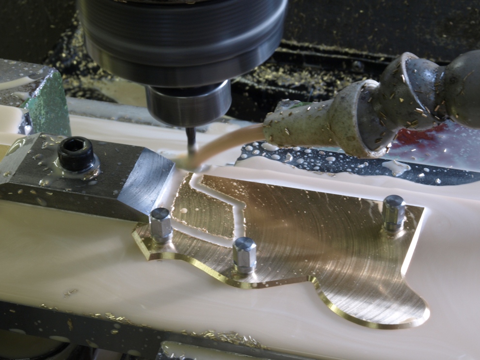
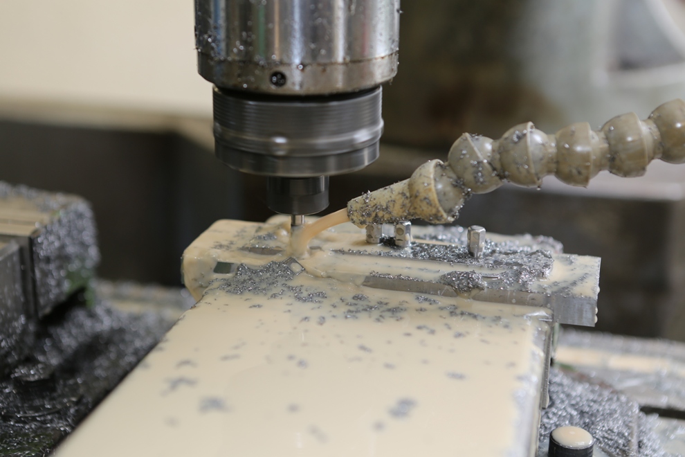
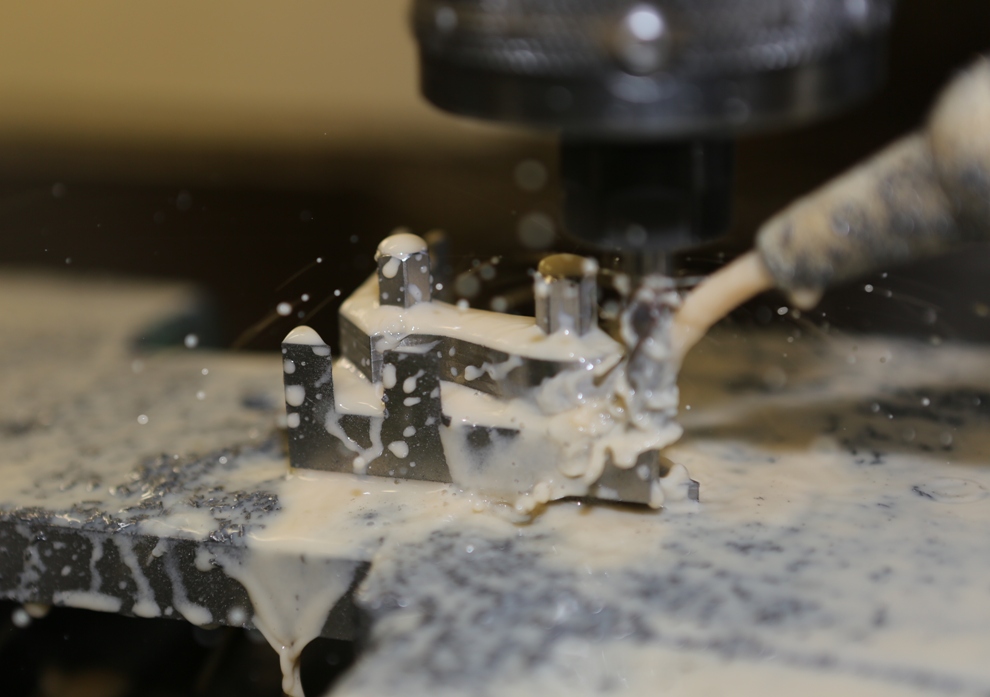
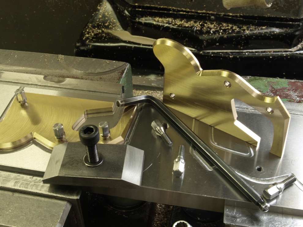
The mouth being cut out last as a separate job as it needs an additional clamping to support the front end – which can be seen to the left hand side of the picture.
 
 
O
 
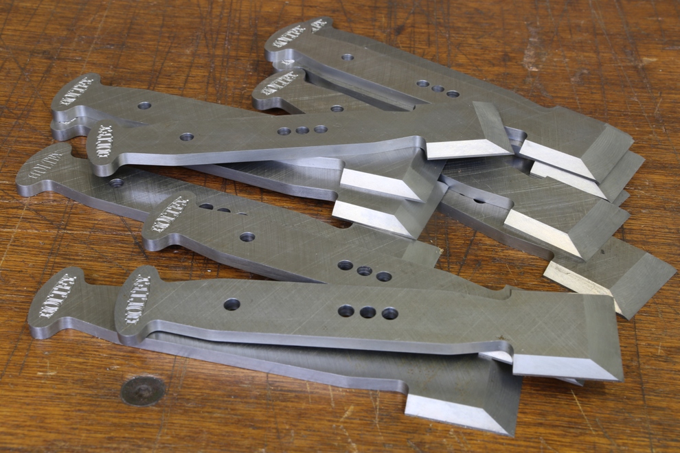
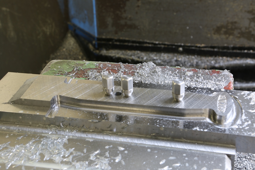
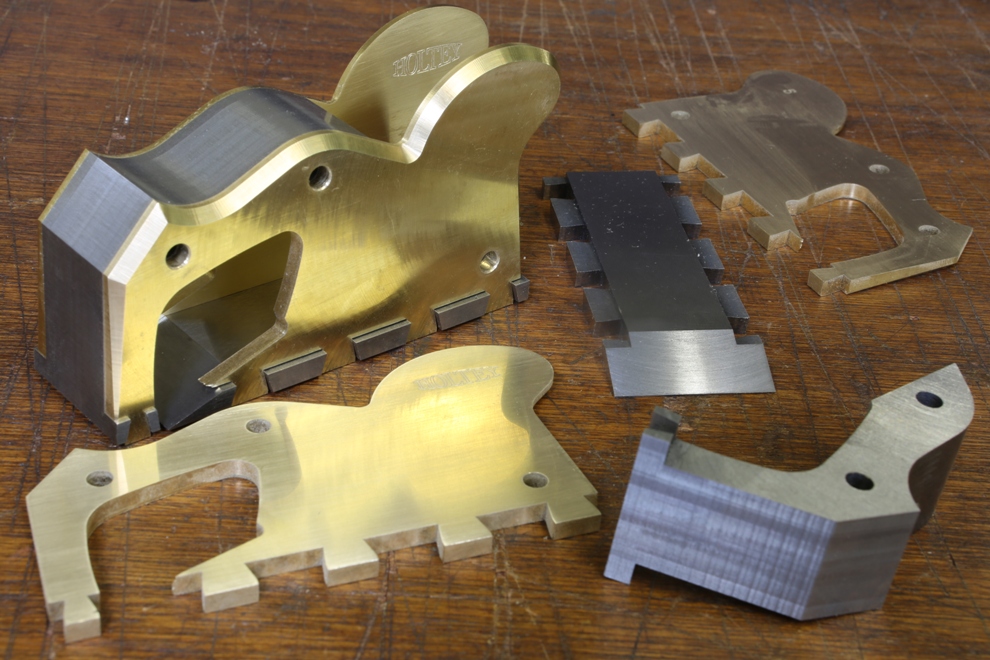
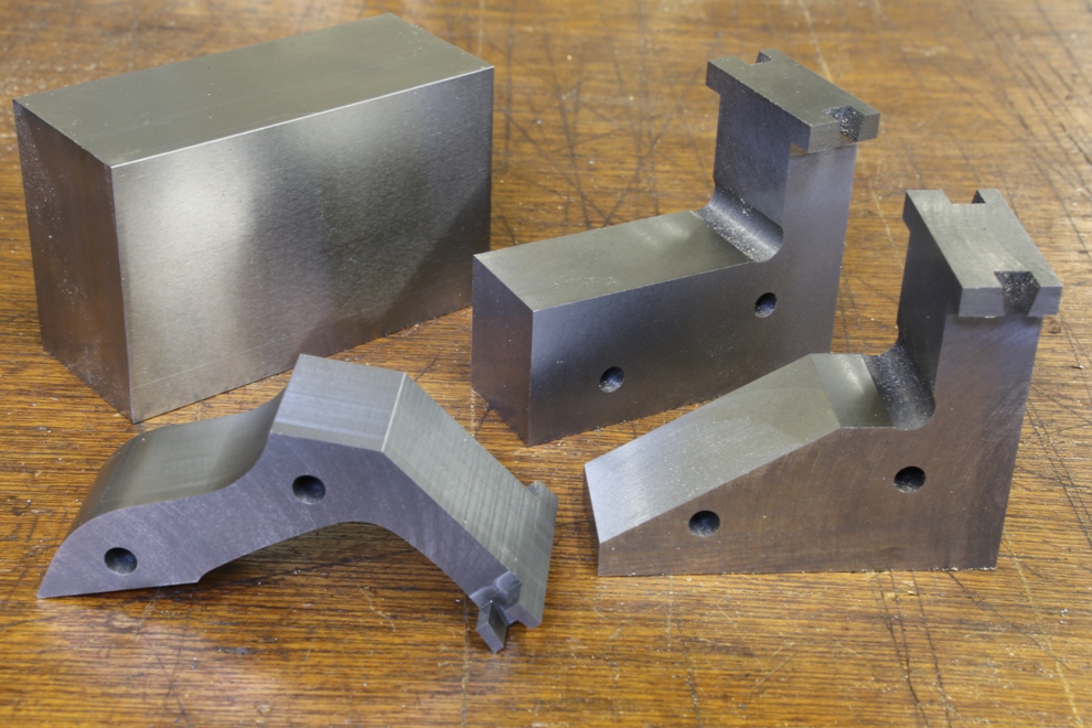
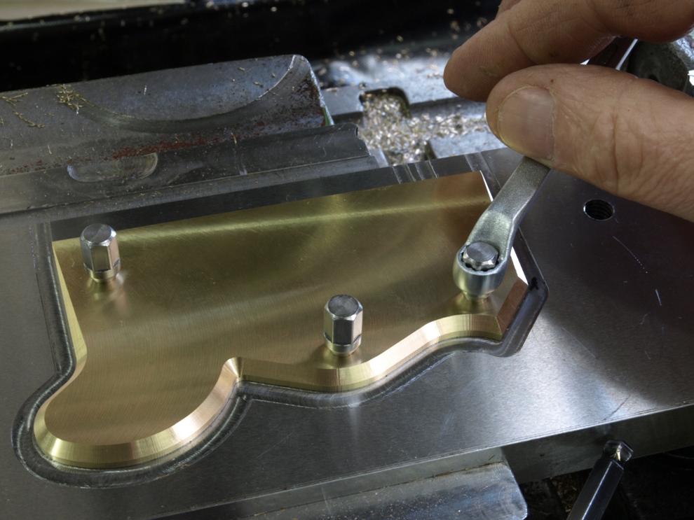
Here is the finished side except for the dovetailing. It includes its mirror partner completing the pair.
 
 
As usual to be continued when I next have an opportunity.

Powered by WordPress