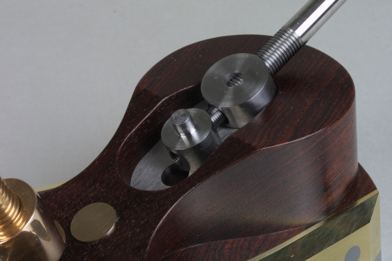
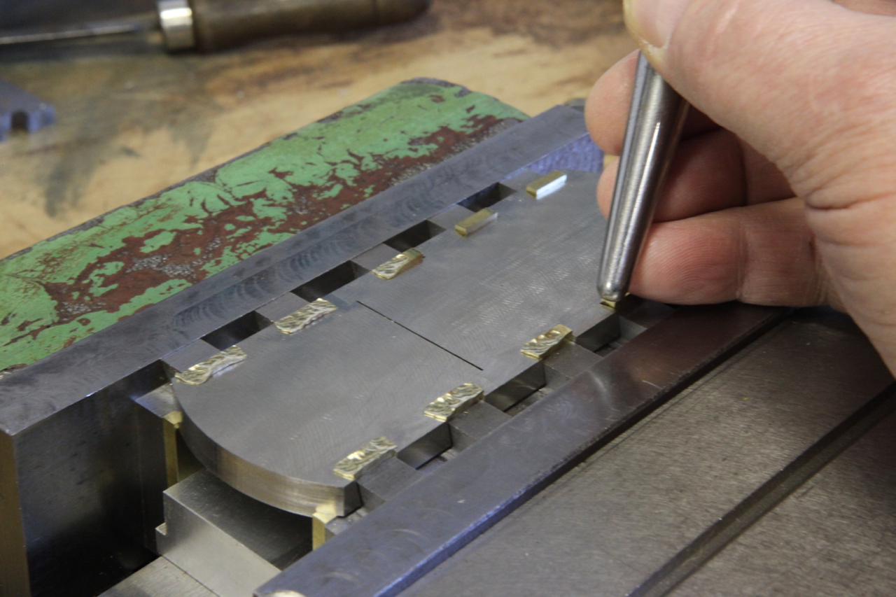
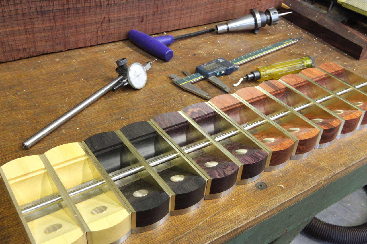
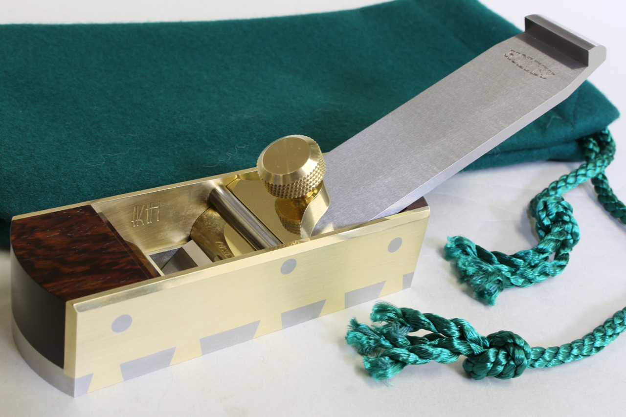
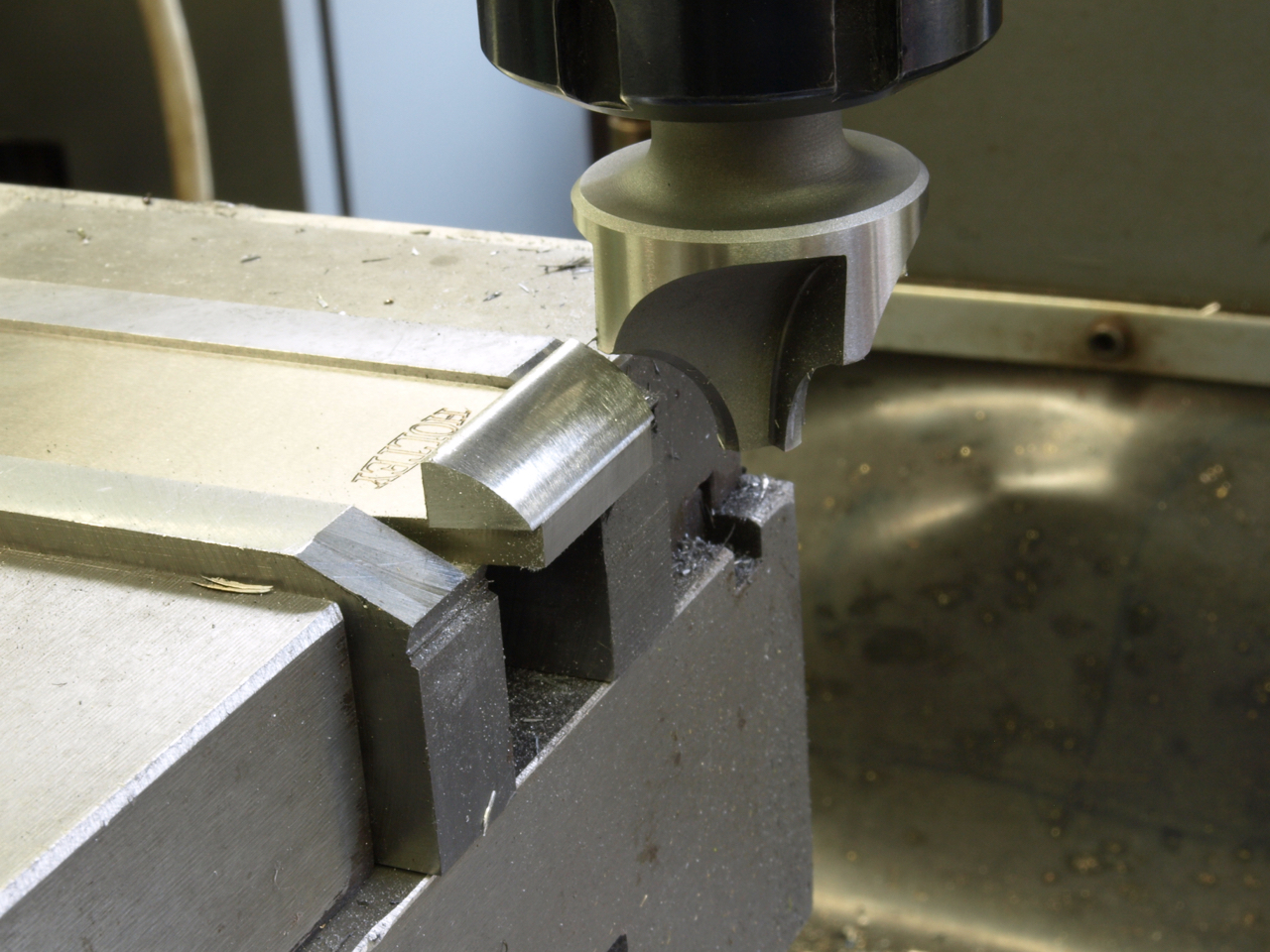
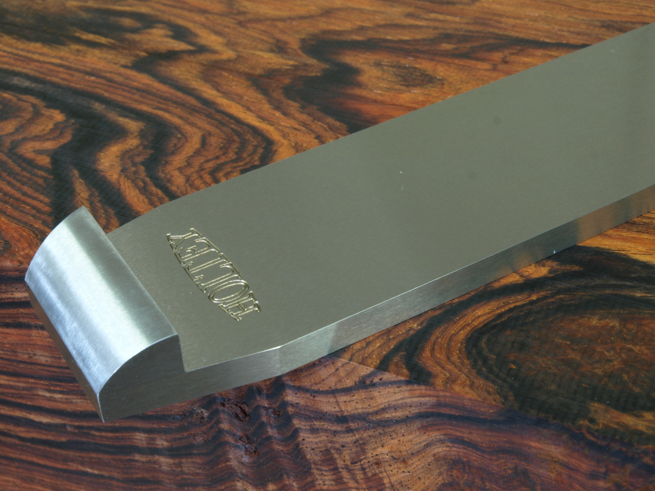
Lets start with dovetailing. The effectiveness of a dovetail must be compounded so that you show a dovetail form on two sides. That means you are going to have a void on one side which will need filling. You will need a bit of extra material left on the ends of the pins and dovetails. This means you have to move the metal around by peining to fill the voids. You have already picked up on my pinch formers and the clamping plates which are made to fit inside the dovetails. All that peining is going to push a lot of things around. Another problem is that there is going to be pressure along the line of dovetails which will then convex the sole. If it doesn’t then you are not peining it hard enough, you want to stuff as much material as possible into those voids. There are good and bad dovetails around. Once everything is all snug and finished there will be a lot of material to flush away and the bottom needs to be flattened on the mill. Also the sides need to be treated in a similar way. I don’t know how far other people go with their dovetailing but this is how I do it. You will notice how true each tail is. All lines are straight and sharp. The former is kept parallel and is the same width as the pinch sides of the bottom. In my language this is a F******g load of work.

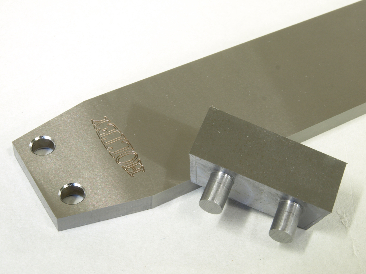
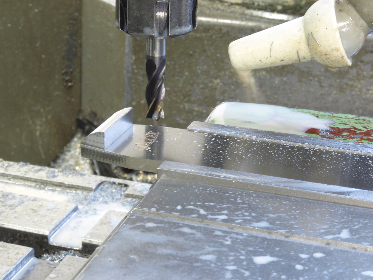
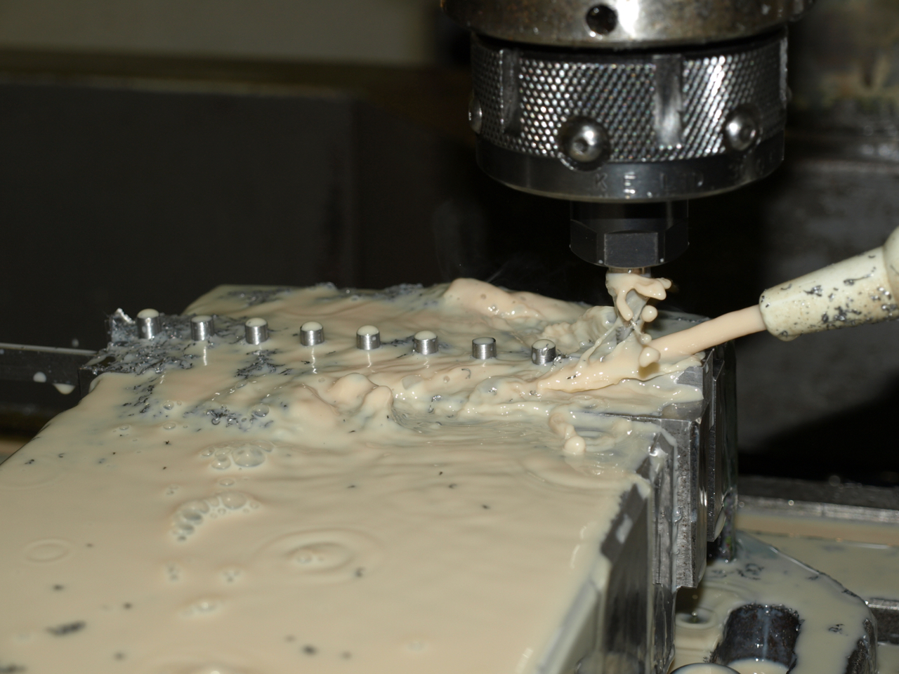
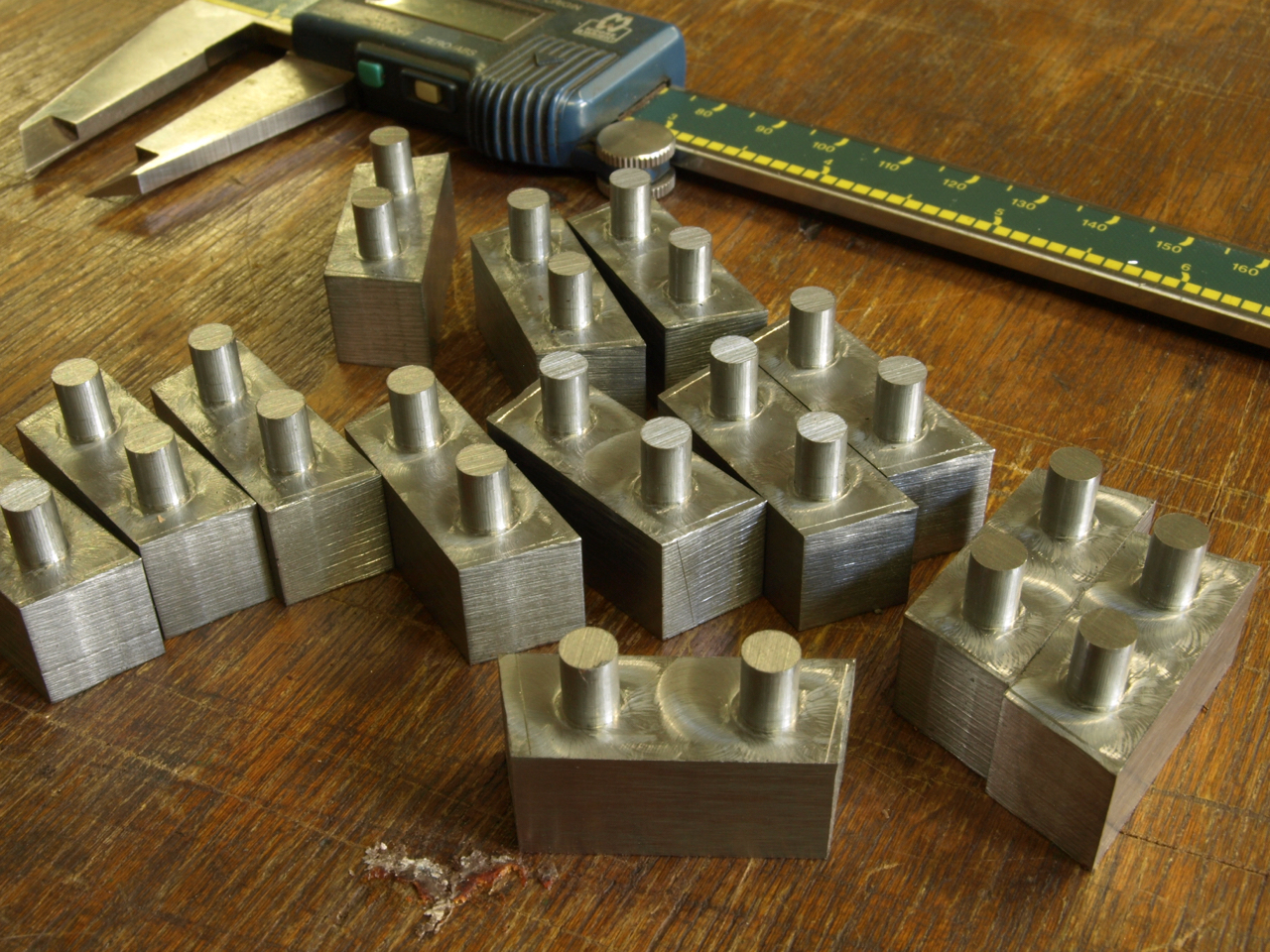
There are two other options. One of these is to form dowels in situ on the bottom which has to be a very accurate process to match with the corresponding holes on the sides. This process needs to be done on a CNC. All in all the work is probably equal to the dovetailing as the peining is a very boring process and has the same effect of causing a lot of pressure with the same problems as above. i.e. you are putting in a lot of stress.
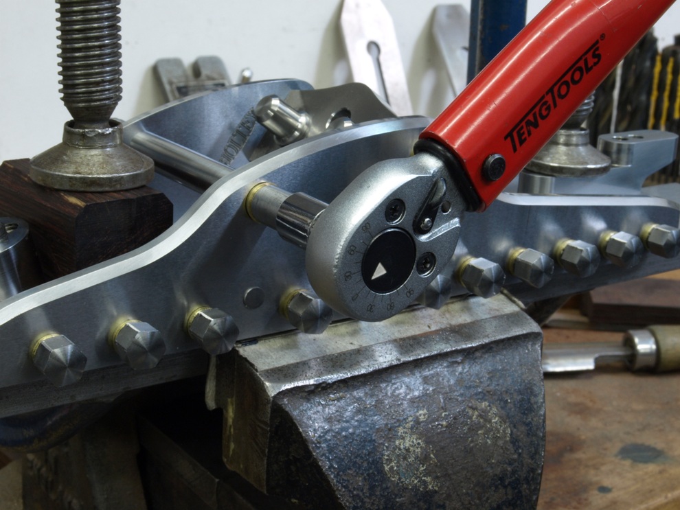
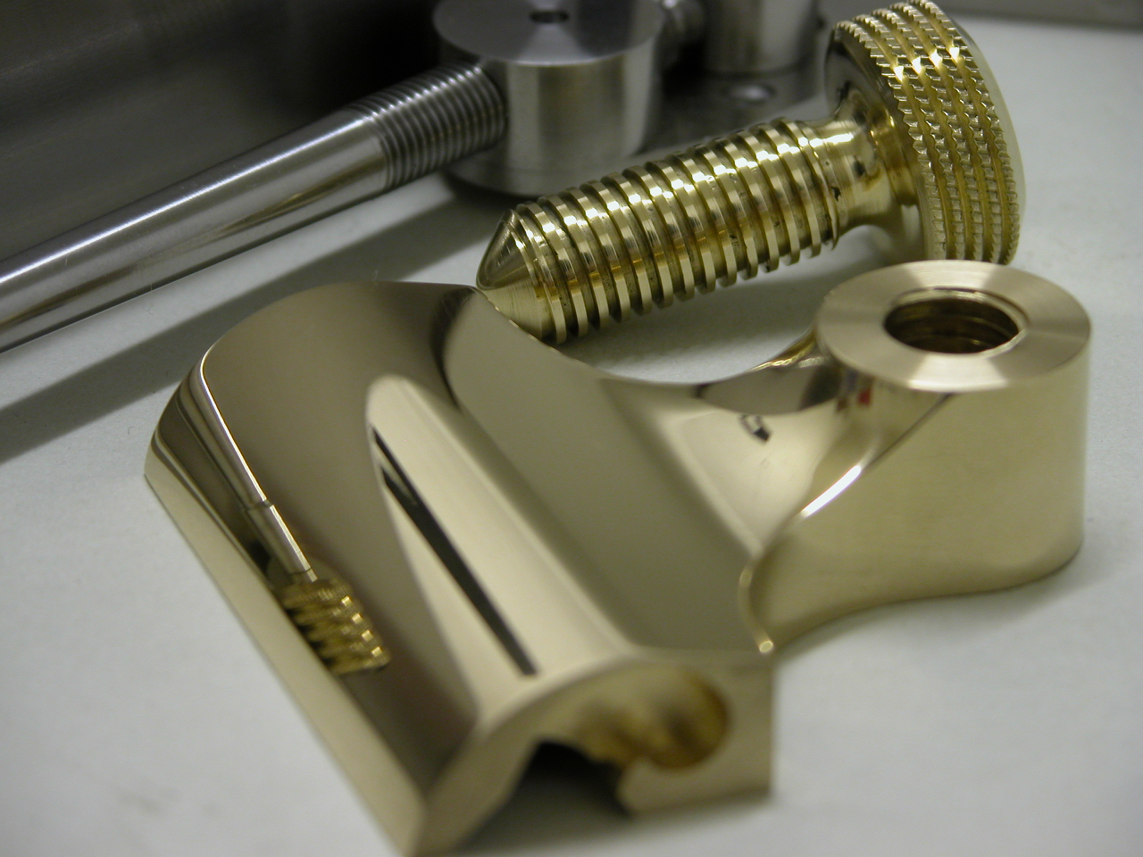
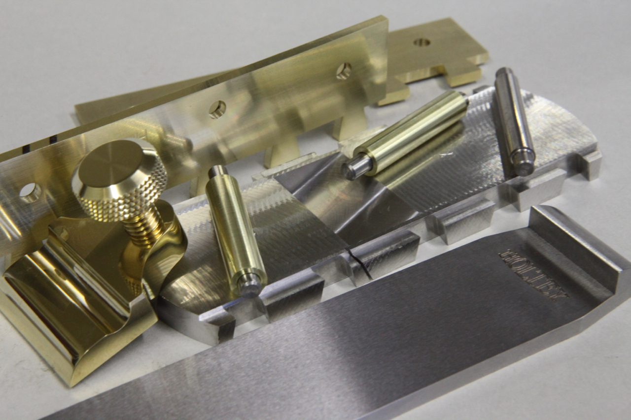
Screwing – is probably a little more work as I am not going to buy a box of screws out of a DIY shop – they are purpose made by me. They have a counter sink angle of 40 deg unlike the 90 deg on a standard screw. Also the screw requires a plain shank as a positioning reference. The heads of the screws need to have a positive drive as they are going to be to a required torque. The angle of the countersink has to be tighter at the top than at the bottom. So as they tighten there will be some metal displacement so there will be no gaps or joints showing. Each screw is then thread locked. With this stage complete the heads can be cut off and the body is then milled true. There is more work in making each screw than one dovetail. But this process has a plus factor by not loading the chassis up with stress.
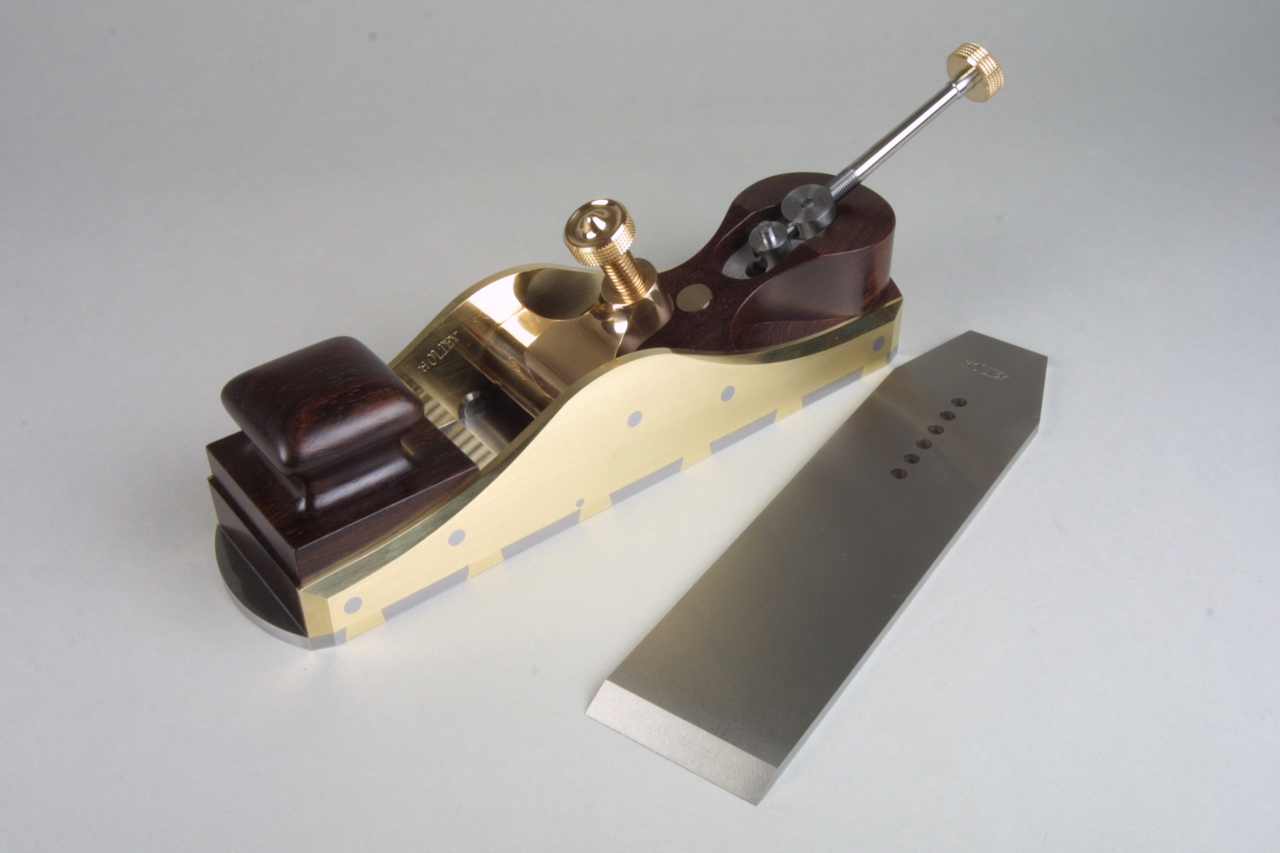
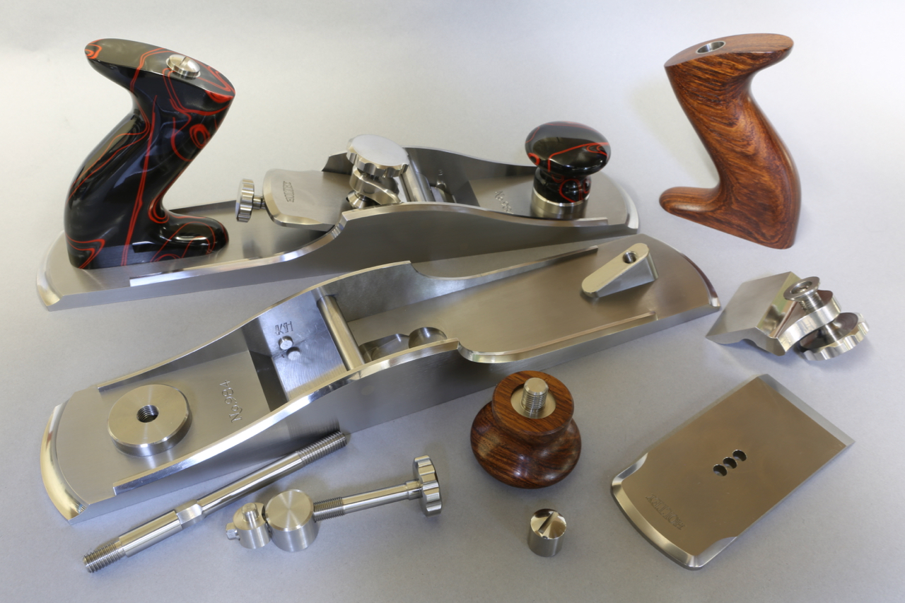
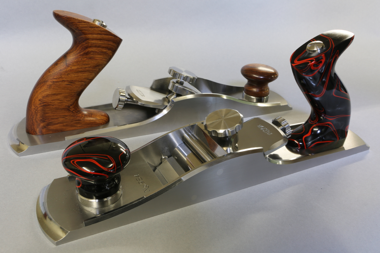
Dovetailing v peining v screwing v in situ doweling
Lets start with dovetailing. The effectiveness of a dovetail must be compounded so that you show a dovetail form on two sides. That means you are going to have a void on one side which will need filling. You will need a bit of extra material left on the ends of the pins and dovetails. This means you have to move the metal around by peining to fill the voids. You have already picked up on my pinch formers and the clamping plates which are made to fit inside the dovetails. All that peining is going to push a lot of things around. Another problem is that there is going to be pressure along the line of dovetails which will then convex the sole. If it doesn’t then you are not peining it hard enough, you want to stuff as much material as possible into those voids. There are good and bad dovetails around. Once everything is all snug and finished there will be a lot of material to flush away and the bottom needs to be flattened on the mill. Also the sides need to be treated in a similar way. I don’t know how far other people go with their dovetailing but this is how I do it. You will notice how true each tail is. All lines are straight and sharp. The former is kept parallel and is the same width as the pinch sides of the bottom. In my language this is a F******g load of work.
There are two other options. One of these is to form dowels in situ on the bottom which has to be a very accurate process to match with the corresponding holes on the sides. This process needs to be done on a CNC. All in all the work is probably equal to the dovetailing as the peining is a very boring process and has the same effect of causing a lot of pressure with the same problems as above. i.e. you are putting in a lot of stress.
Screwing – is probably a little more work as I am not going to buy a box of screws out of a DIY shop – they are purpose made by me. They have a counter sink angle of 40 deg unlike the 90 deg on a standard screw. Also the screw requires a plain shank as a positioning reference. The heads of the screws need to have a positive drive as they are going to be to a required torque. The angle of the countersink has to be tighter at the top than at the bottom. So as they tighten there will be some metal displacement so there will be no gaps or joints showing. Each screw is then thread locked. With this stage complete the heads can be cut off and the body is then milled true. There is more work in making each screw than one dovetail. But this process has a plus factor by not loading the chassis up with stress.