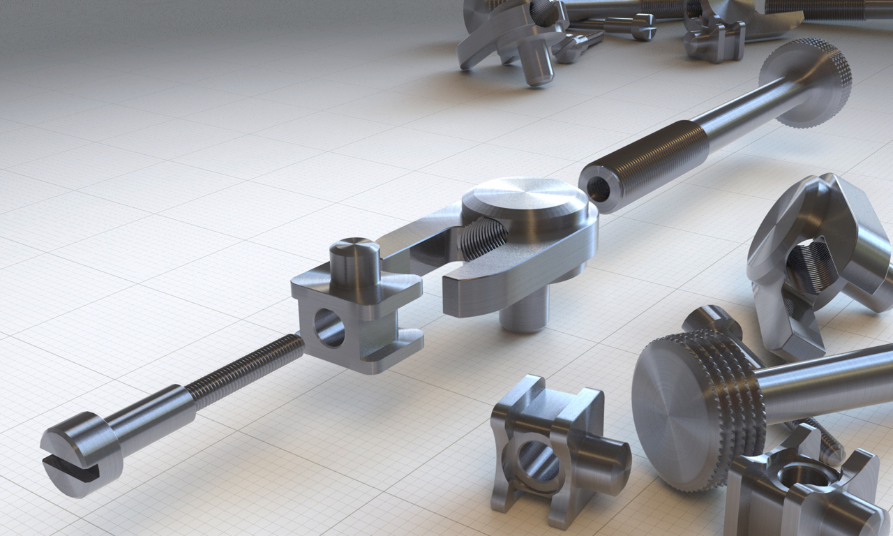
These are some renders of my A1 panel plane that Adam Willis has created for me
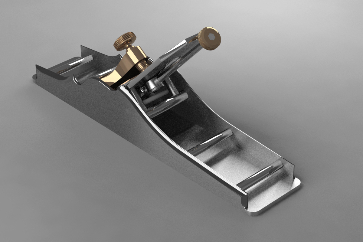
These are some renders of my A1 panel plane that Adam Willis has created for me
Holtey improved pattern mitre plane, Norris and Spiers style. But with an adjuster
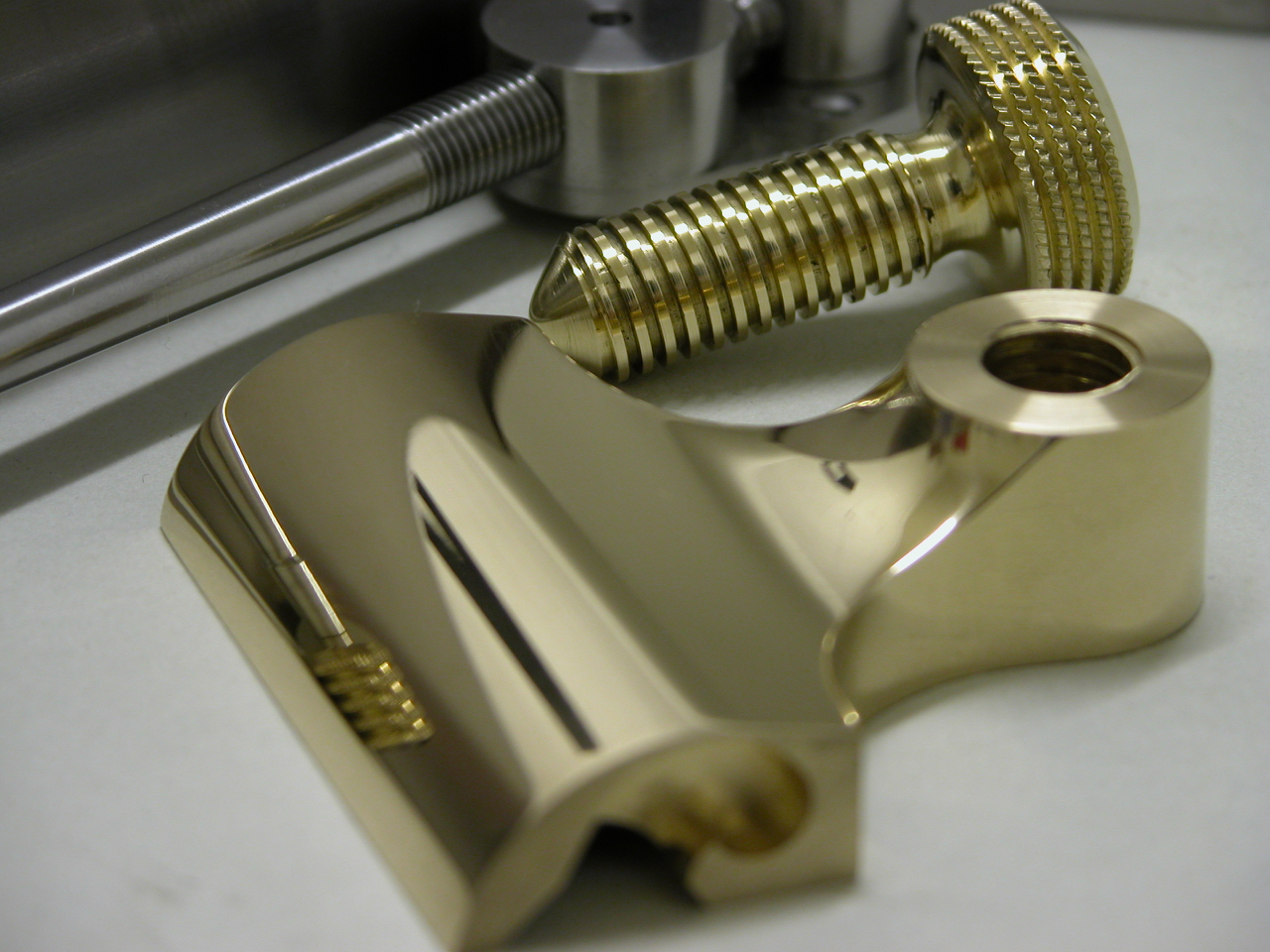
Lever cap for improved pattern mitre plane
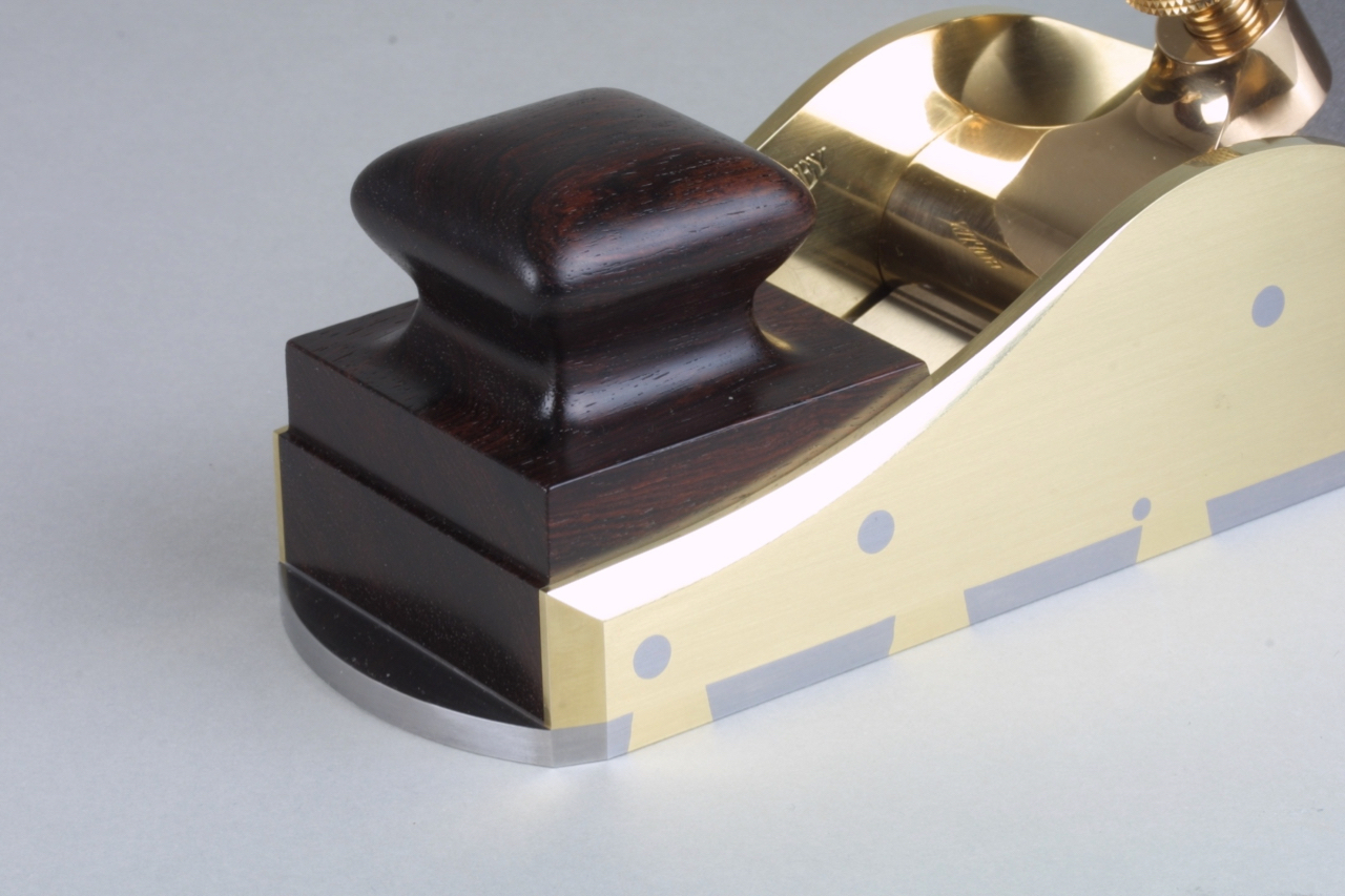
Improved pattern Mitre plane showing bun
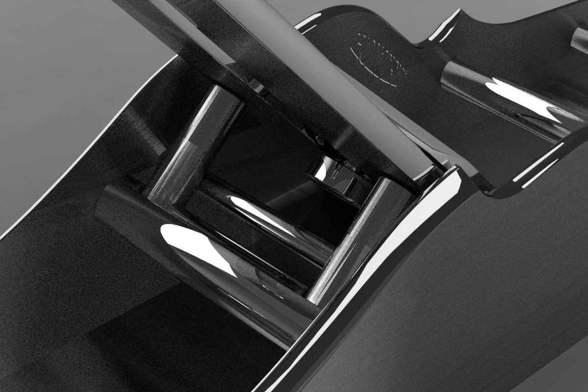
improved pattern mitre plane with adjuster, rear view
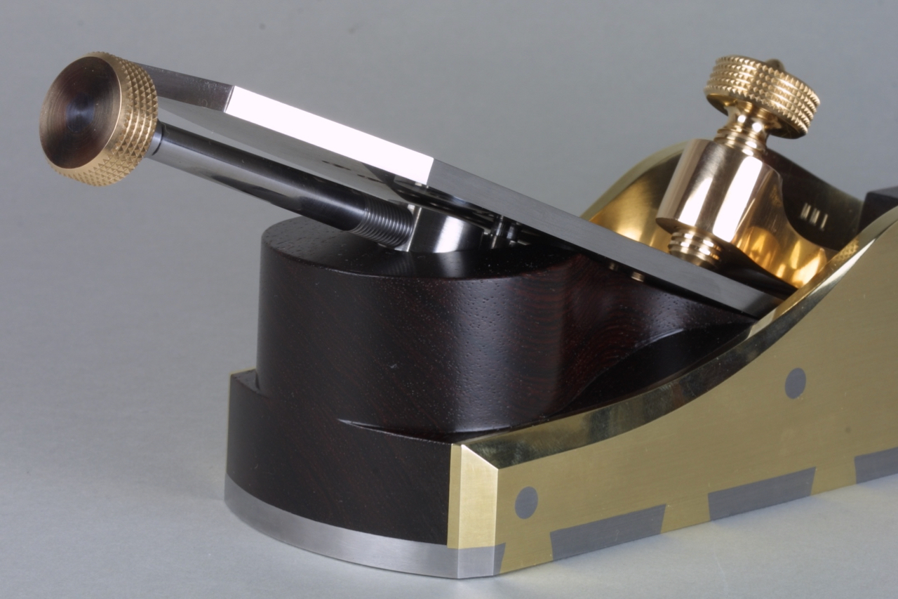
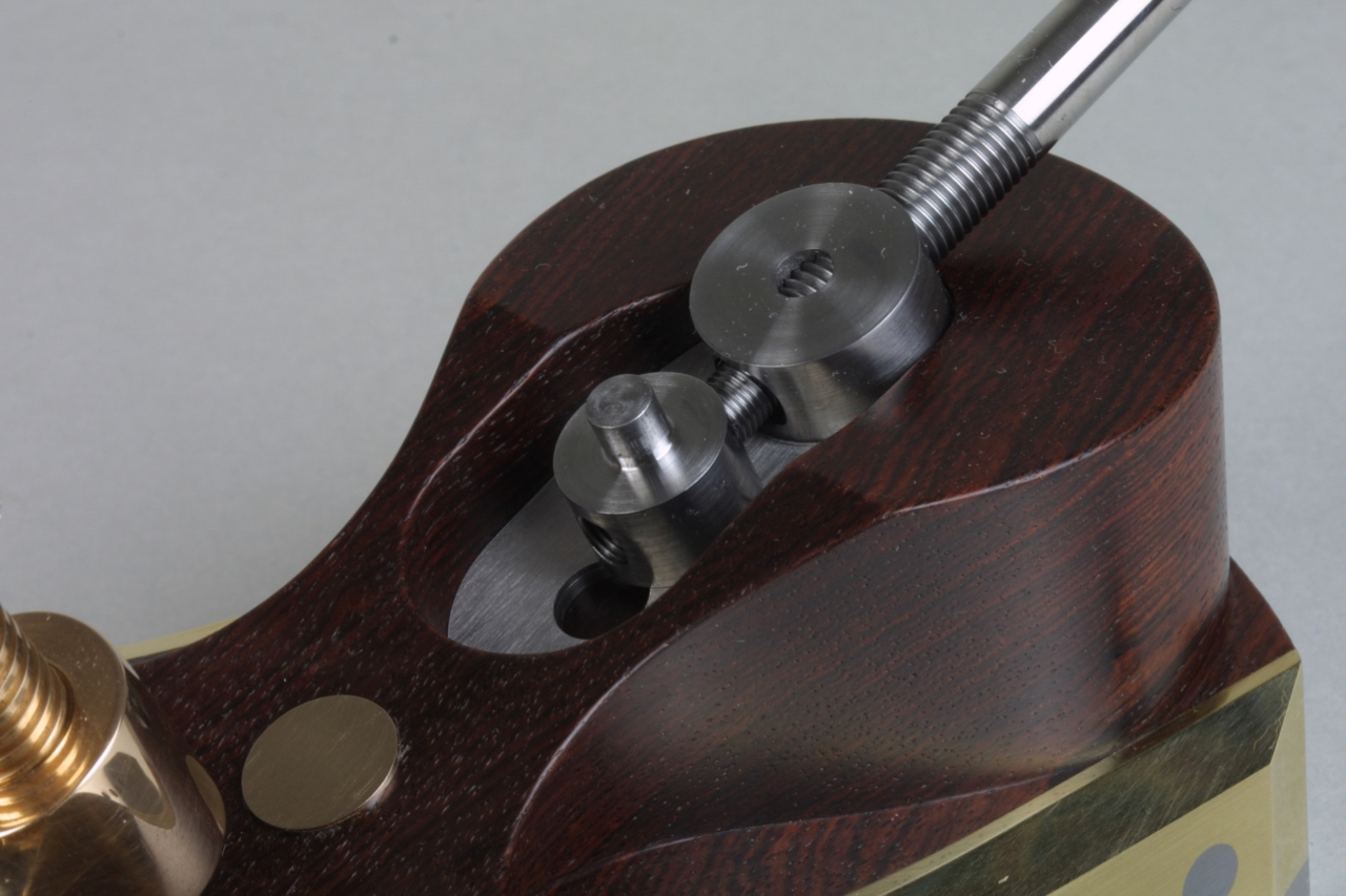
showing adjuster in it’s recess
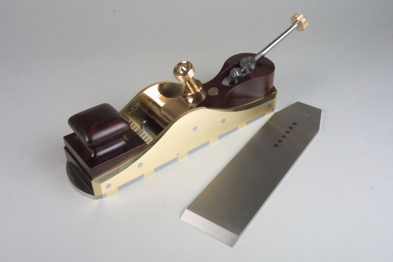
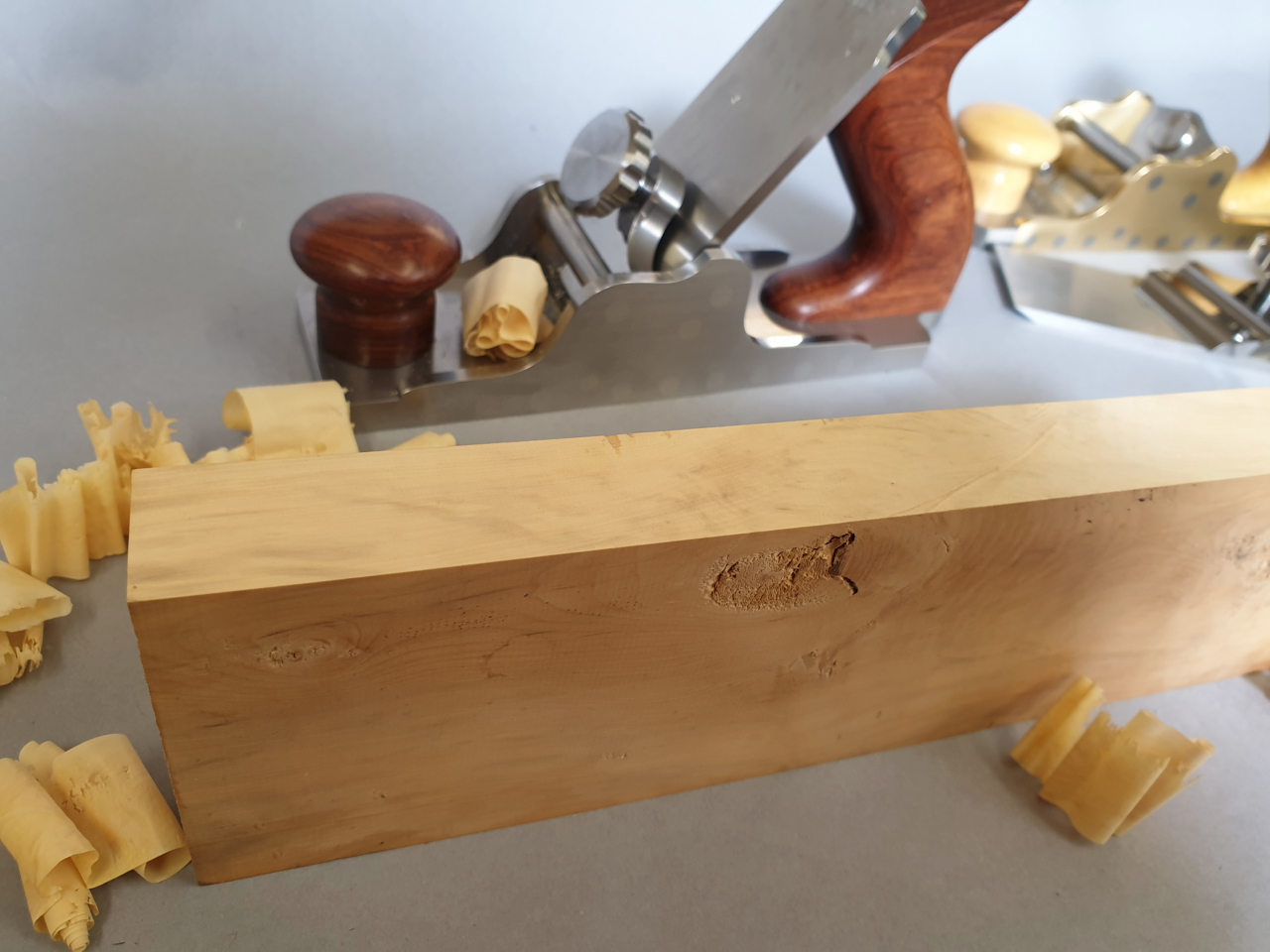
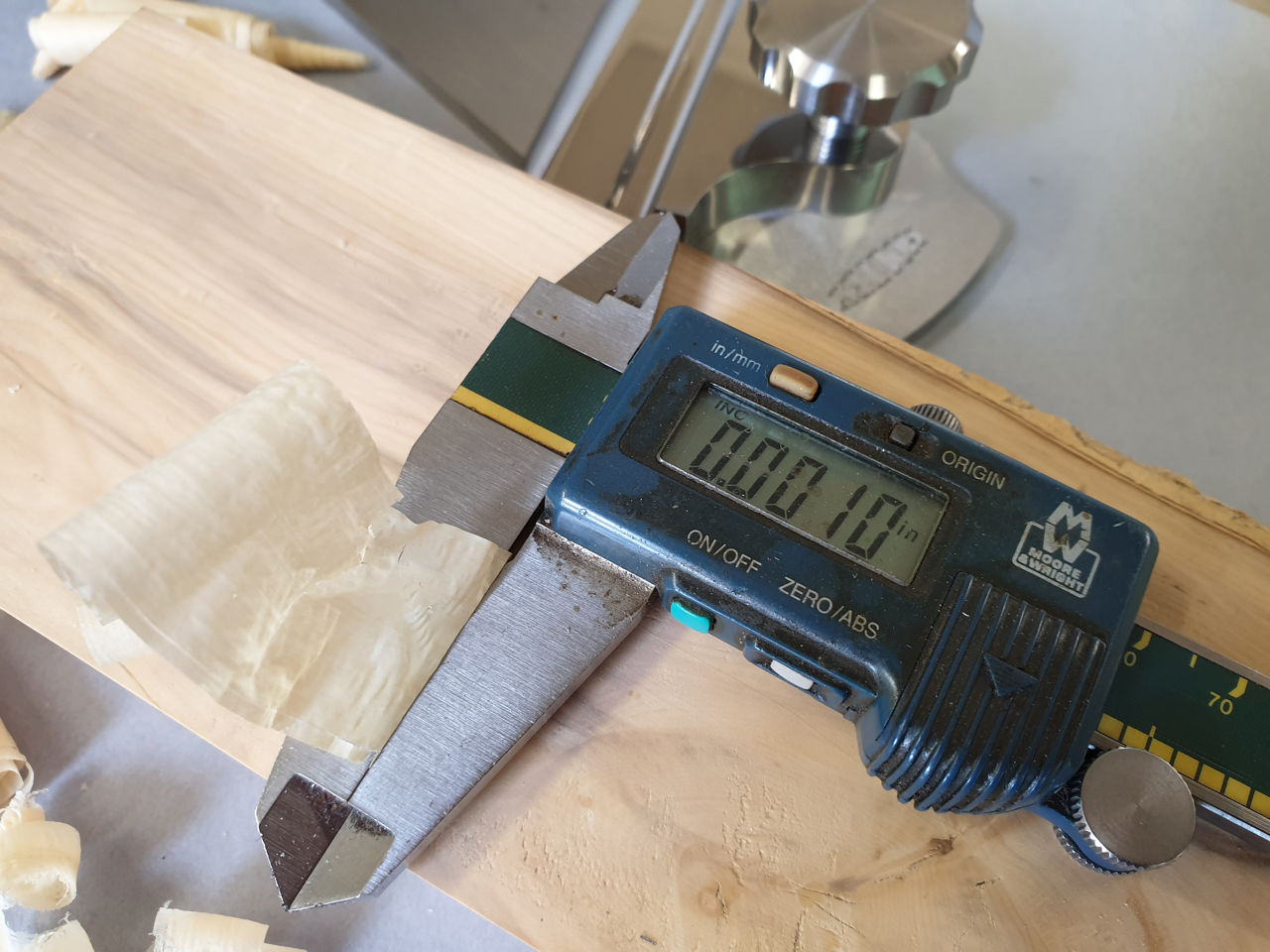
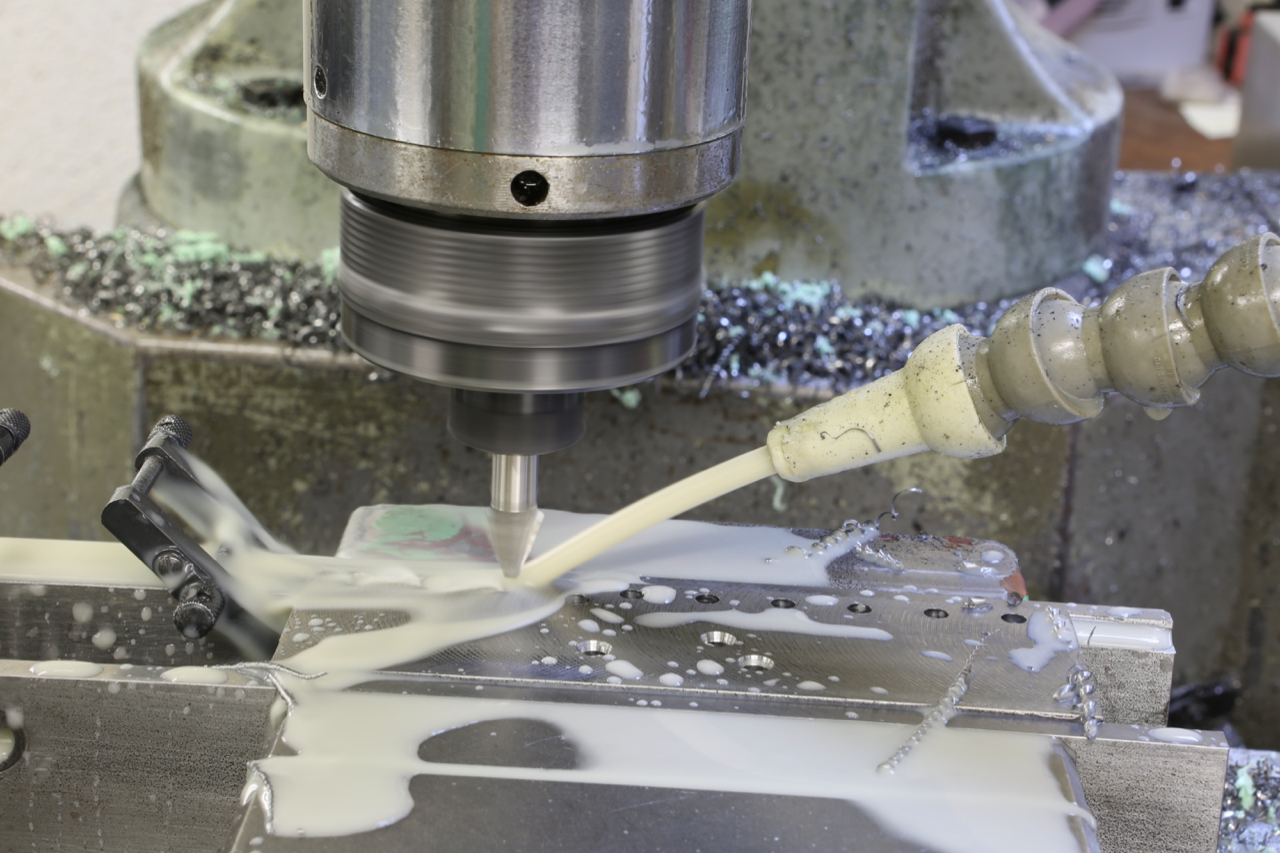
This is unusual for me because I think showing off shavings could be a little sad. Not many people tell you the wood they are using but here I have planed a very wild piece of Boxwood out of the scrap bin. As you can see there is a large knot near the edge so there is a lot of alternating grain. I was pushing off quite a thick shaving at 2 thou with no tear out at all. Then I was able to finish off at 1 thou without revisiting the oil stone. No doubt the enthusiast could improve on this performance as I don’t have the time to play. This is my new blade in stainless – that is all I am saying.
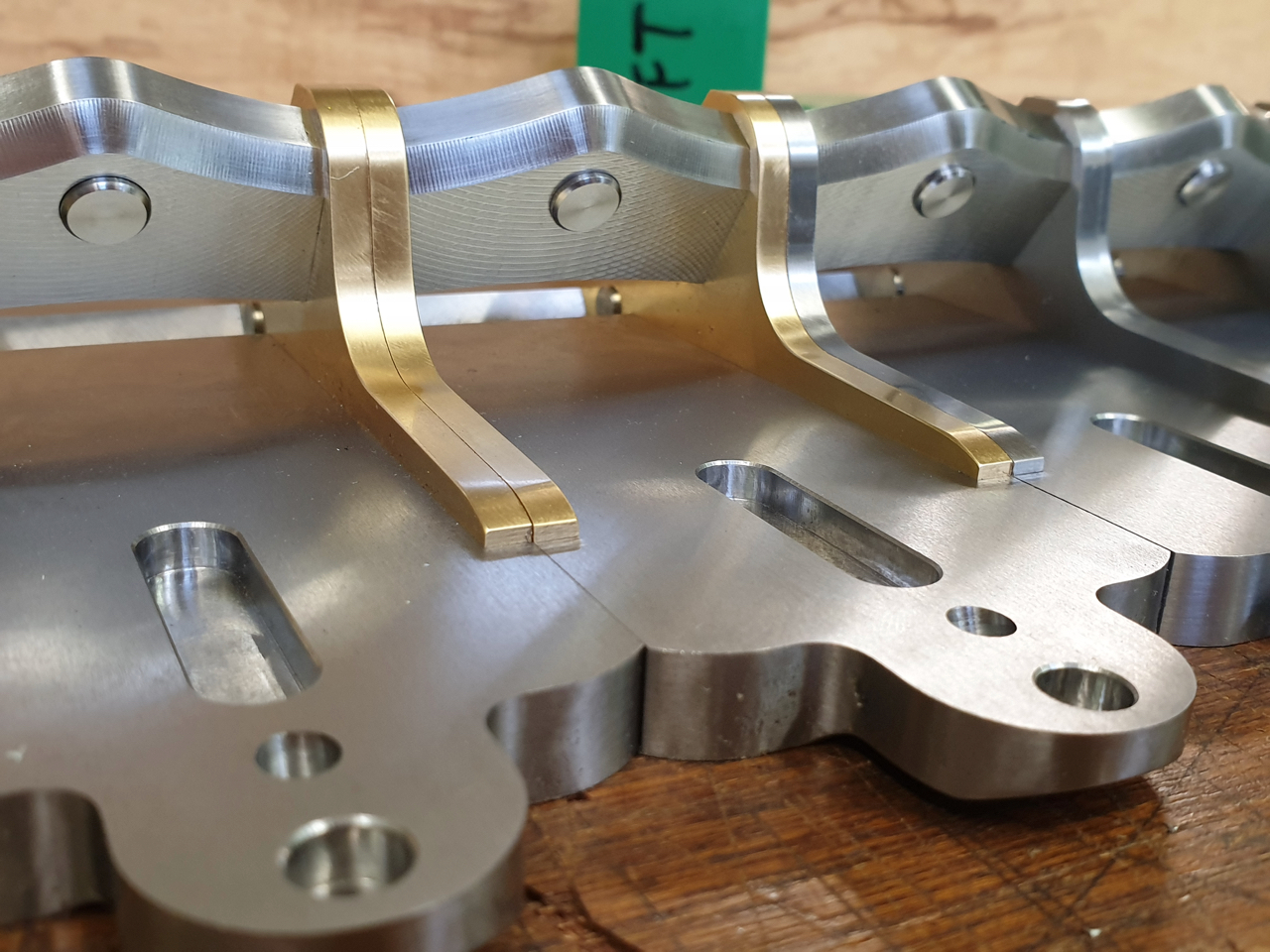
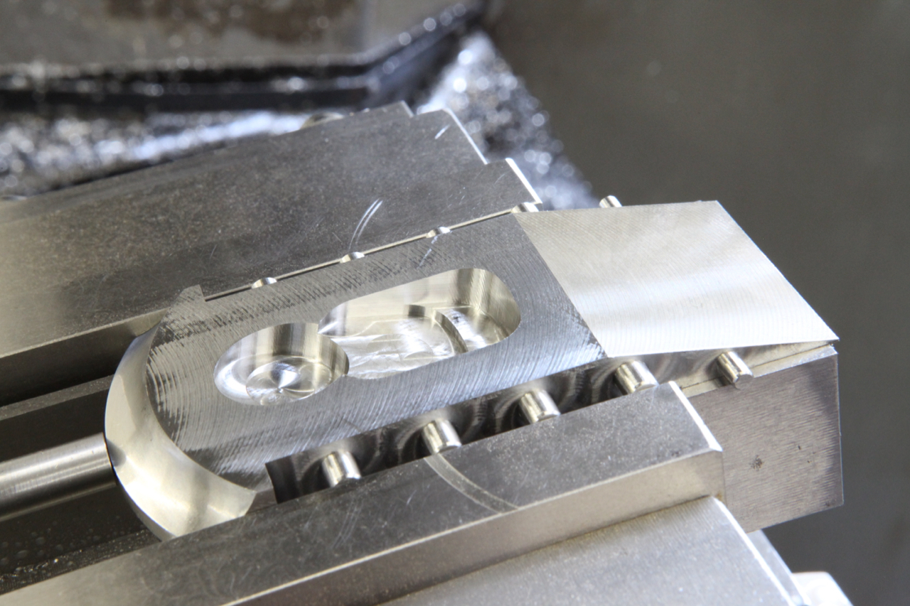
Photos showing the bolts trimmed, milled and surface ground. This plane has probably been the best of all my work and one of the most important factors is the much heavier chassis. I have been able to work to very much tighter milling tolerances, in fact well under 1 thou. It has helped on the grinding because I need to take less off – stainless steel is very difficult for grinding and I can only take cuts of .0002″ (that is 2/10 of a thou). The more cuts you take from stainless the harder the material becomes. You also have to be continually wheel dressing even with using a ceramic wheel. This is the real work that I enjoy the most.
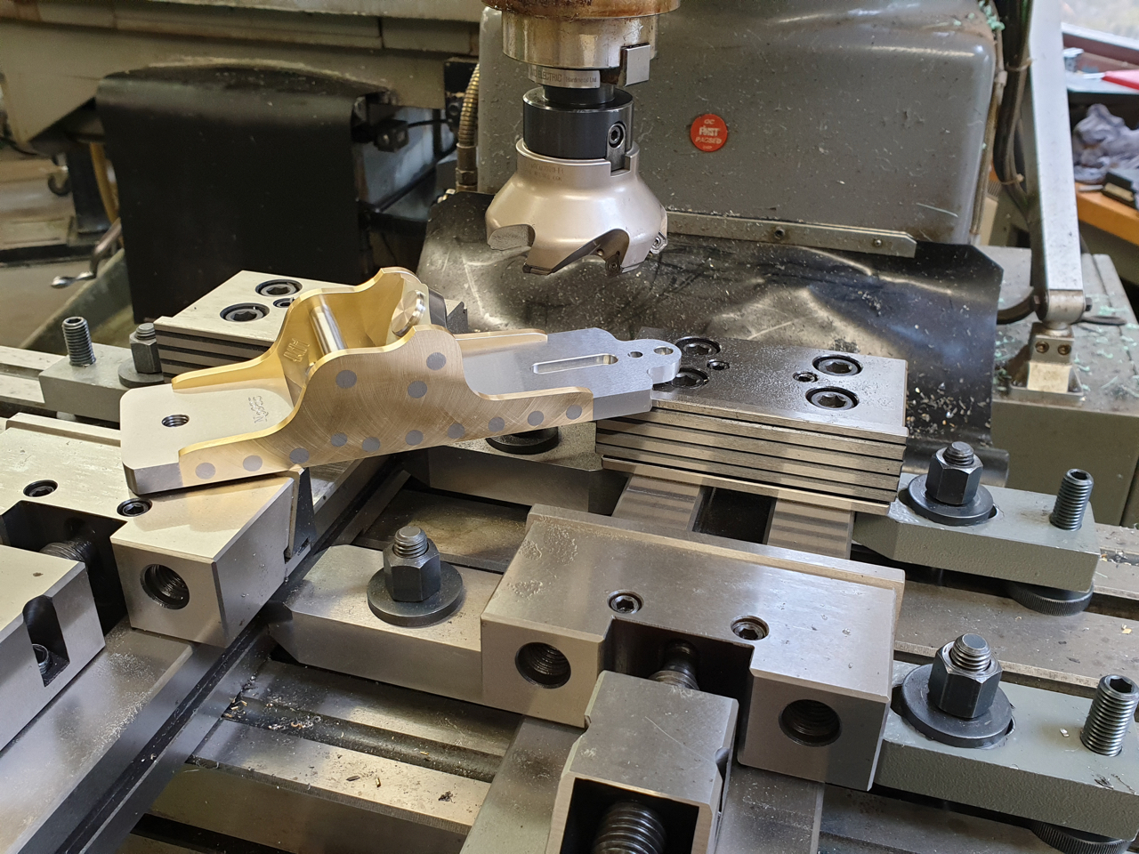
Setting up for the completion of the rear handle carrier.
The handle carrier now finished with drilling and counterbore and with streamlining facet.
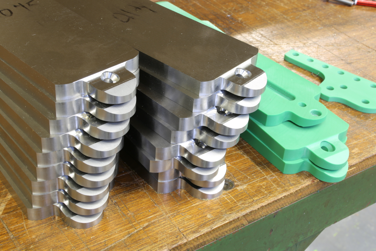
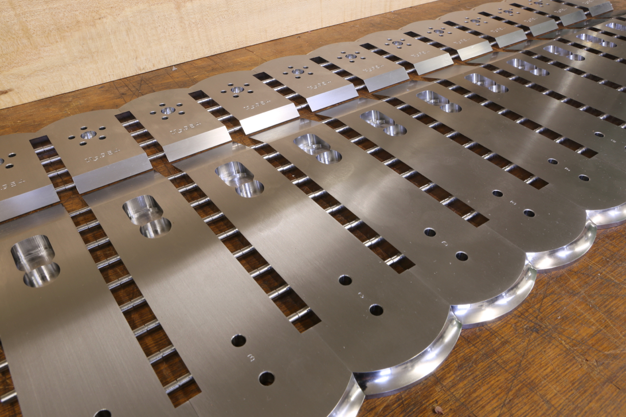
Work commences on the stainless sides … you didn’t really think I was going to make it out of green plastic?
After a milling operation is finished everything has to be broken down and set up again for the next stage. This usually means making new fixtures and writing another programme. Always a lot of understated work on every new design.
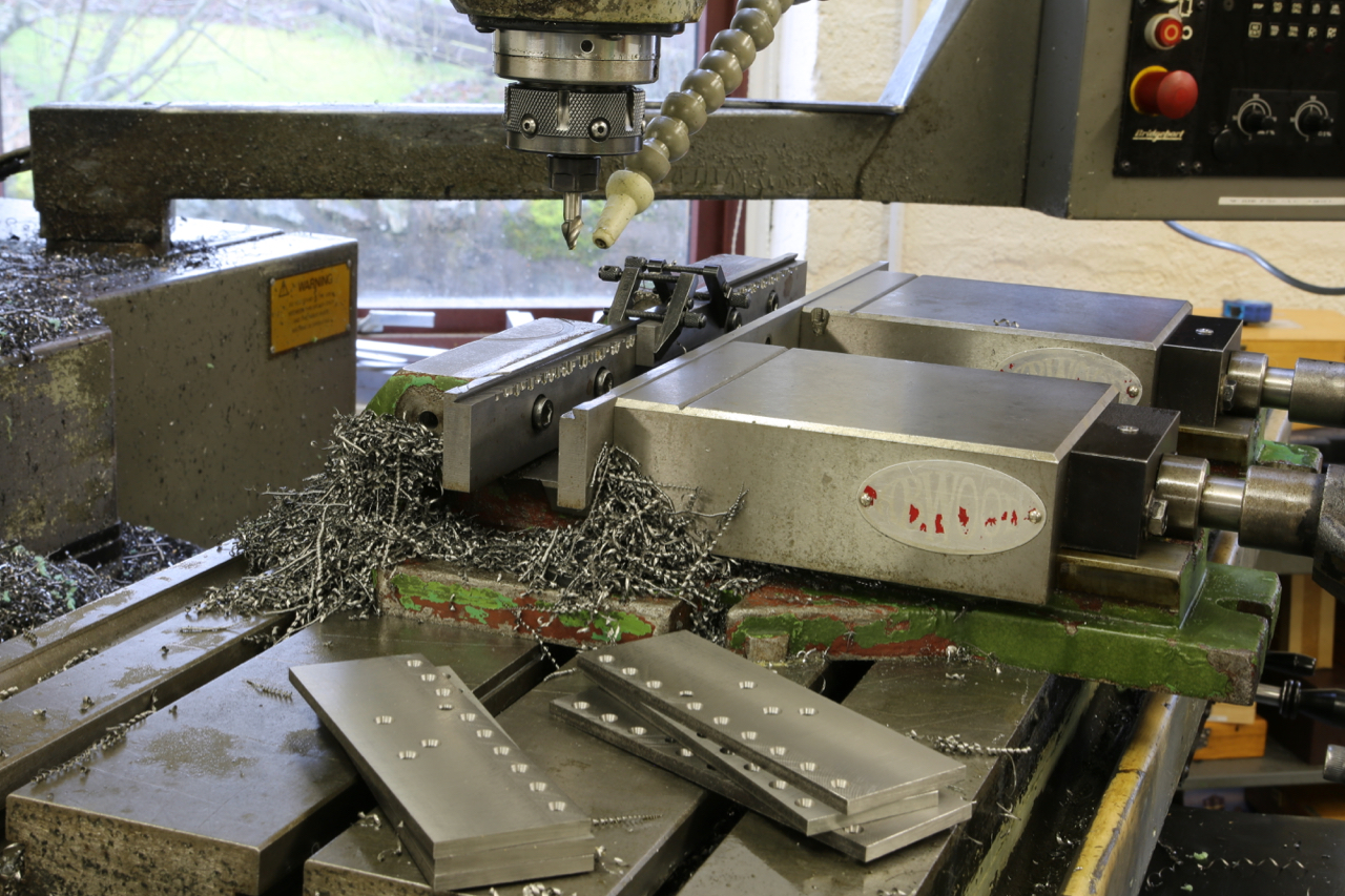
It is always sad breaking down the machine just when everything seems to be working nicely. I have to be extra careful I haven’t missed out a side (done it before!).
One of the things that makes me different is that this is not just a craft job, this work is precision and takes a lot of planning.
I have decided to try and keep everyone informed as to the detailed work that goes into these planes. A well known manufacturer once said that I always manage to keep my work hidden.
I couldn’t find this picture earlier on, but it has now appeared
This is one of the best adjuster I have ever made, and I hope to revisit this but it is only suitable for a bevel down plane
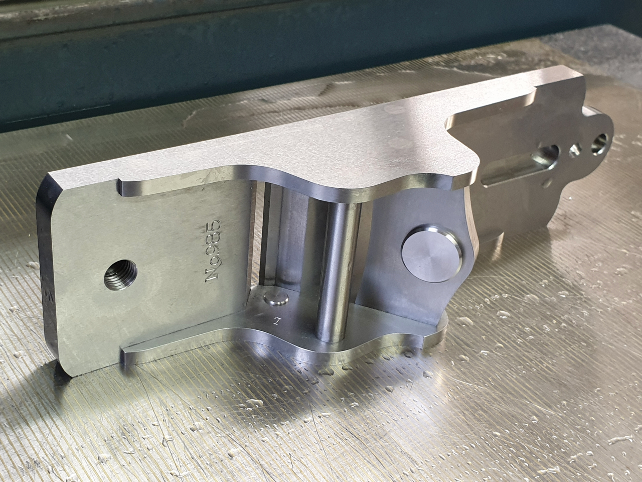
I still keep revisiting the drawing board making final adjustments to my new plane the No 985 – seems to go on forever. Whilst I have been doing this I have been making comparisons between non-adjuster planes and adjuster planes and I am working on the basis that having an adjuster does double the price. I will try to explain the difference and why the work compounds.
Since designing my own planes I have moved on a long way from the earlier Norris examples. The Norris planes with their adjusters did tend to be a bit basic, like most planes of this time, almost bordering on primitive. You could literally recess the infill and drop the adjuster straight in, securing with two wood screws.
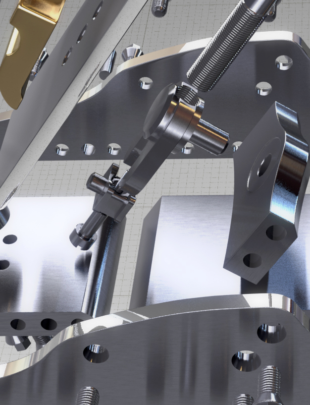
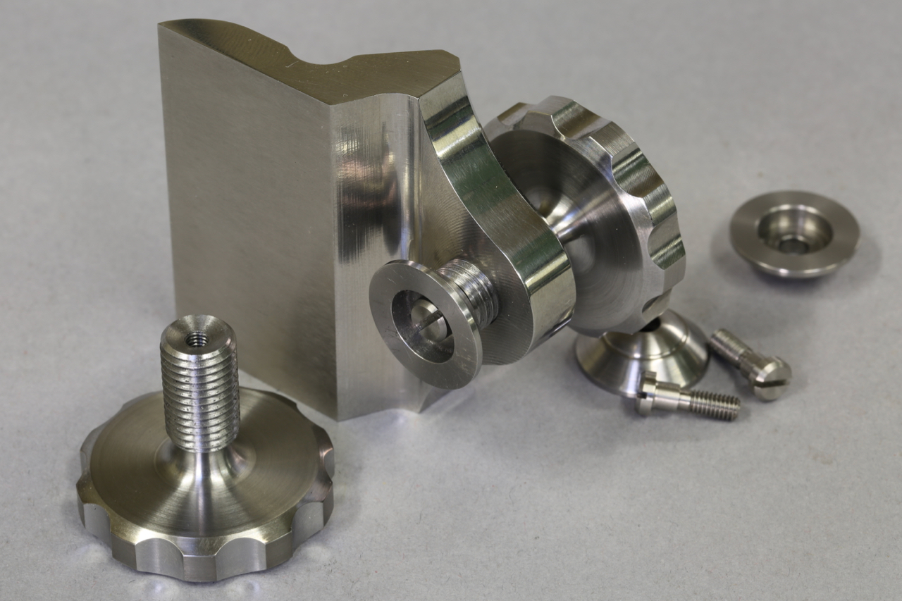
I will explain with an example of where a lot of the work goes, which doesn’t appear to have much to do with the actual adjuster. My adjuster designs are truly integrated into the plane, I don’t just pop an adjuster in as an extra!
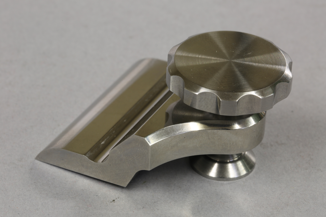
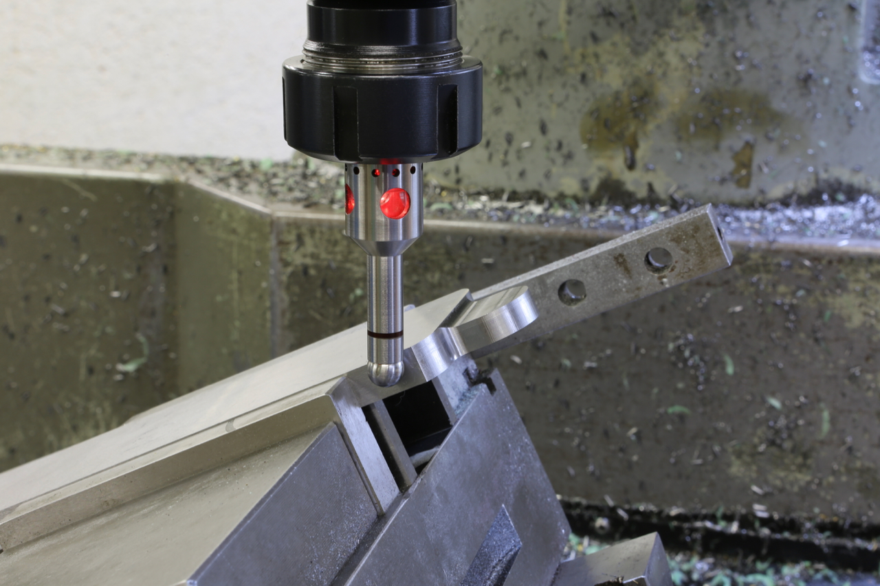
The photo below shows the swivel which is balled so it matches any irregularities whilst connecting with the blade. This is, like most of my design elements, my own innovation.
As you can see the lever cap (from my No 984 plane which is blogged here:http://www.holteyplanes.com/blog/category/no-984/, showing the machine working) is stepped/recessed so that it will carry a swivel. This is necessary with adjuster planes as the swivel shoe will bridge the adjuster holes in the blade. From my research it appears that I am probably the first pioneer to drop the chip breaker on bevel down planes. The first plane I made like this was the 11-s (see photo)
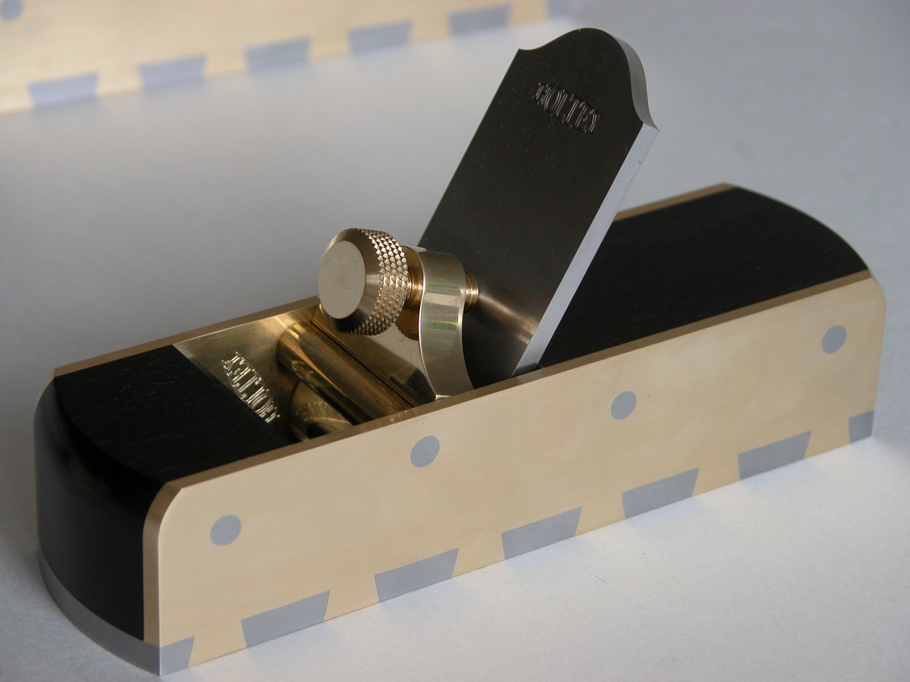
As the 11s has no adjuster drillings the lever cap was quite straight forward and less work. When I made the No 982 I was able to avoid the holes in the blade with the lever cap placement but it put some limitations on the design.
This is an example of the adjuster recessing in the No 983.
This is the bottom for the No 984 showing the adjuster recess.
In summary: to add an adjuster, both adjuster and plane have to be truly integrated. Of course the adjuster has to be made as well.
Powered by WordPress
Dovetailing v peining v screwing v in situ doweling
Lets start with dovetailing. The effectiveness of a dovetail must be compounded so that you show a dovetail form on two sides. That means you are going to have a void on one side which will need filling. You will need a bit of extra material left on the ends of the pins and dovetails. This means you have to move the metal around by peining to fill the voids. You have already picked up on my pinch formers and the clamping plates which are made to fit inside the dovetails. All that peining is going to push a lot of things around. Another problem is that there is going to be pressure along the line of dovetails which will then convex the sole. If it doesn’t then you are not peining it hard enough, you want to stuff as much material as possible into those voids. There are good and bad dovetails around. Once everything is all snug and finished there will be a lot of material to flush away and the bottom needs to be flattened on the mill. Also the sides need to be treated in a similar way. I don’t know how far other people go with their dovetailing but this is how I do it. You will notice how true each tail is. All lines are straight and sharp. The former is kept parallel and is the same width as the pinch sides of the bottom. In my language this is a F******g load of work.
There are two other options. One of these is to form dowels in situ on the bottom which has to be a very accurate process to match with the corresponding holes on the sides. This process needs to be done on a CNC. All in all the work is probably equal to the dovetailing as the peining is a very boring process and has the same effect of causing a lot of pressure with the same problems as above. i.e. you are putting in a lot of stress.
Screwing – is probably a little more work as I am not going to buy a box of screws out of a DIY shop – they are purpose made by me. They have a counter sink angle of 40 deg unlike the 90 deg on a standard screw. Also the screw requires a plain shank as a positioning reference. The heads of the screws need to have a positive drive as they are going to be to a required torque. The angle of the countersink has to be tighter at the top than at the bottom. So as they tighten there will be some metal displacement so there will be no gaps or joints showing. Each screw is then thread locked. With this stage complete the heads can be cut off and the body is then milled true. There is more work in making each screw than one dovetail. But this process has a plus factor by not loading the chassis up with stress.