Was it really Christmas Eve since I last blogged!!!!!!
The first batch of planes are now finished, they were not easy but it hasn’t taken me 10 solid weeks to get this far.
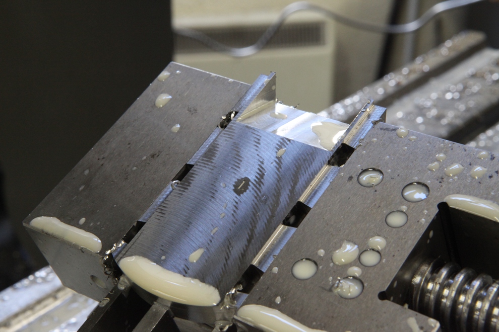
I seem to have landed here without any pictures of separating the bottoms into front and rear. This picture now shows the beds being milled. There is a surprising amount of material to move and has cost me a considerable amount in tooling. Stainless steel does have its disadvantages.
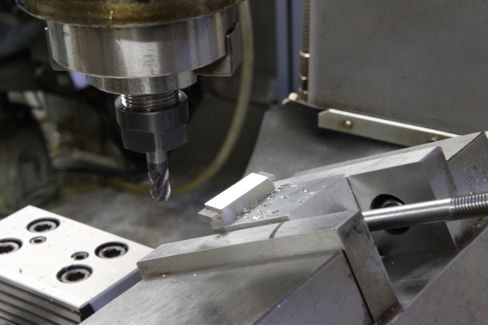
The front end of the bottom. There are two operations here. The first one is to machine the angle for the front end of the mouth then a small rebate is machined to catch the sides of the mouth from the rear section. This will lend a desirable amount of support, especially when it comes to peining the dovetails otherwise this part of the dovetail will cave into the mouth. It also provides additional rigidity to the plane body because any stresses could force the two halves of the plane to jiggle. It doesn’t sound very technical but it is descriptive. It could show a step where the front and the rear of the bottom join. Of course we are only talking very small amounts here (+/- 2 thou).
Something that always amuses me on the traditional mitres is the tongue and groove joint. This does absolutely nothing.
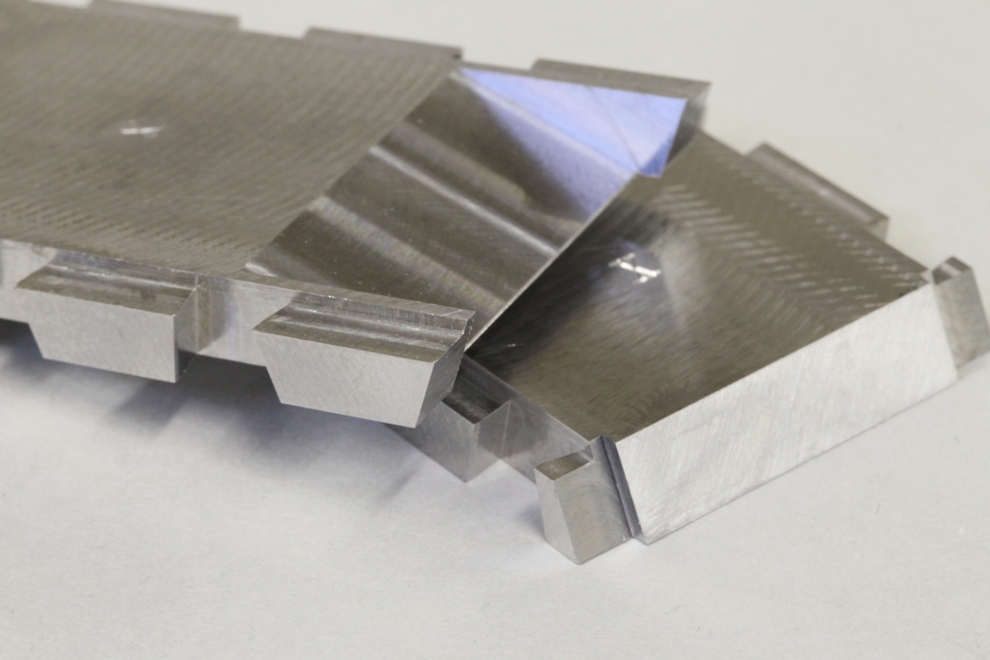
The jointing from the front and rear and bed detail.
Very critical because when it goes together everything must be in the right position for the dovetails. Also the joint between the front and the rear needs to be just right – tight but not over tight. The blade bed has to be in the exact position as well. When everything is assembled and the bottom and sides are skimmed flush the dovetails want to look tidy with no visible joint and the mouth with the blade in position needs to be dammed close to the desired setting. It takes the patience of Job to get all the settings. Once you have the settings right you don’t want to stop; wish I had a thousand lined up to do (I don’t want to come back here again in too much of a hurry).
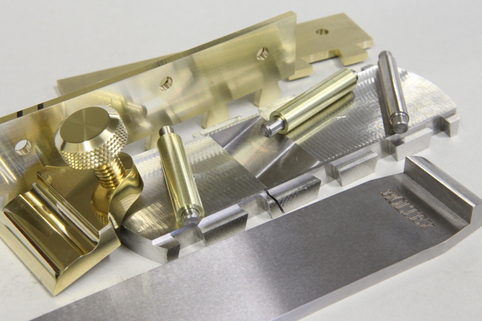
A few of the components ready for assembly. The previously described jointing shows up well in this picture.
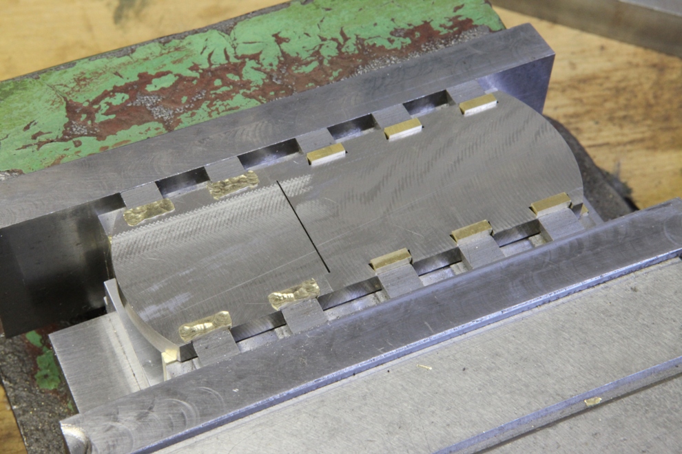
Starting the peining process.
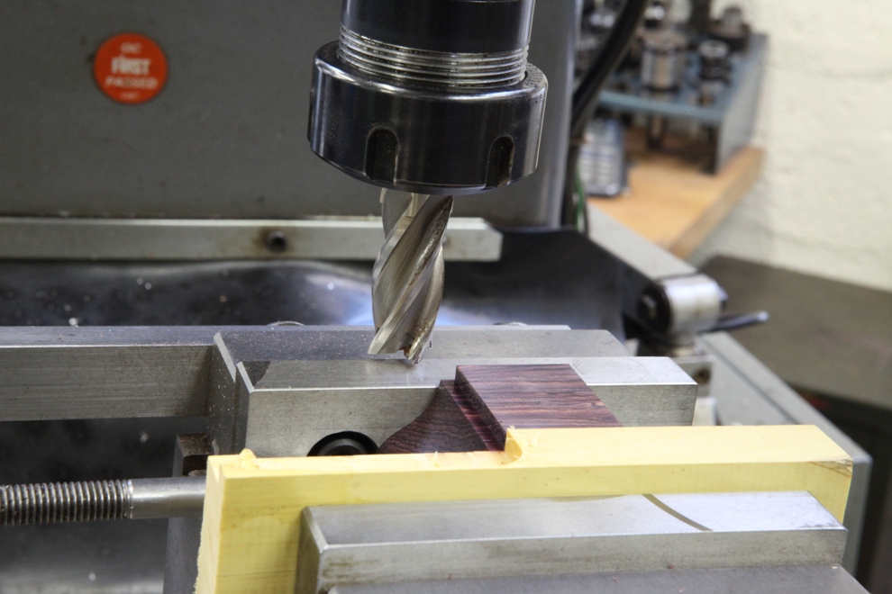
Machining the quirk (the small rebate detail) in the throat area of the plane.
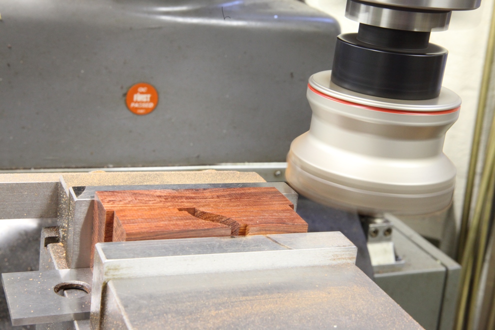
I have missed photographing a lot of work on the infills. Here are two of the front infills being planed in the mill for the final fit between the plane sides. I always allow extra width of these infills for the fitting purpose and the possibility of further shrinkage. It seems to me no matter how dry the wood appears it always seem to change/move. This is definitely the bane of an infill plane.
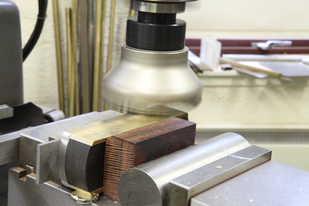
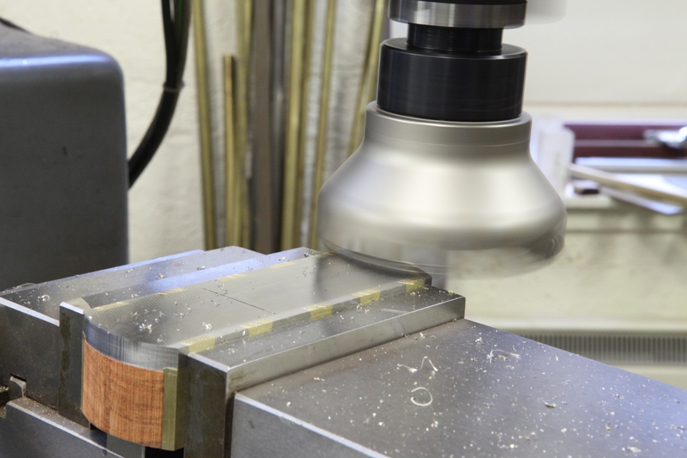
With the infills riveted in place, the picture shows the mill being used once more to plane the sides and bottoms flush.
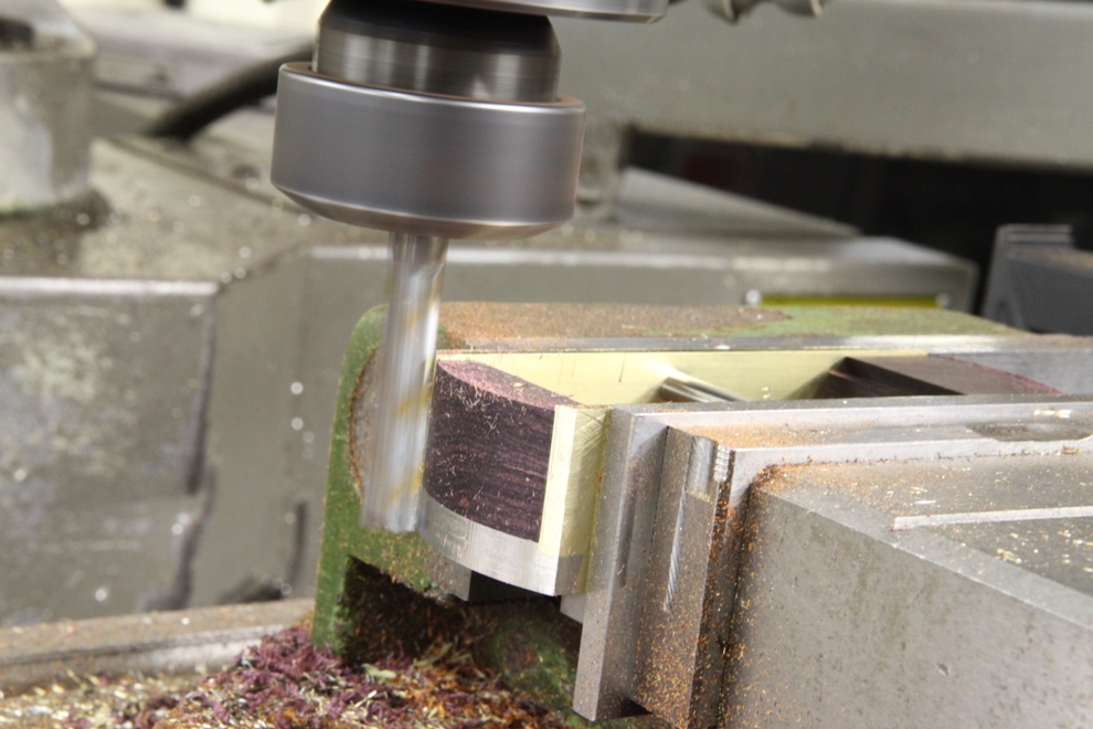
The front and back end are rounded with the use of my CNC mill with a simple programme. Wouldn’t like to do this job any other way, it leaves a true circle and creates a minimal amount of polishing. Polishing can sometimes lose the sharp form.
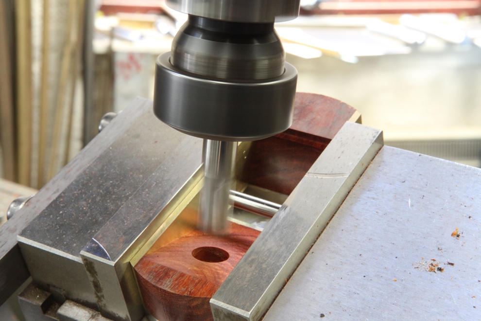
This shows the boring for the rear of the blade bed. This goes through the wood and partly into the stainless steel bottom to take the brass insert which is cut from a 9/16” brass bar.
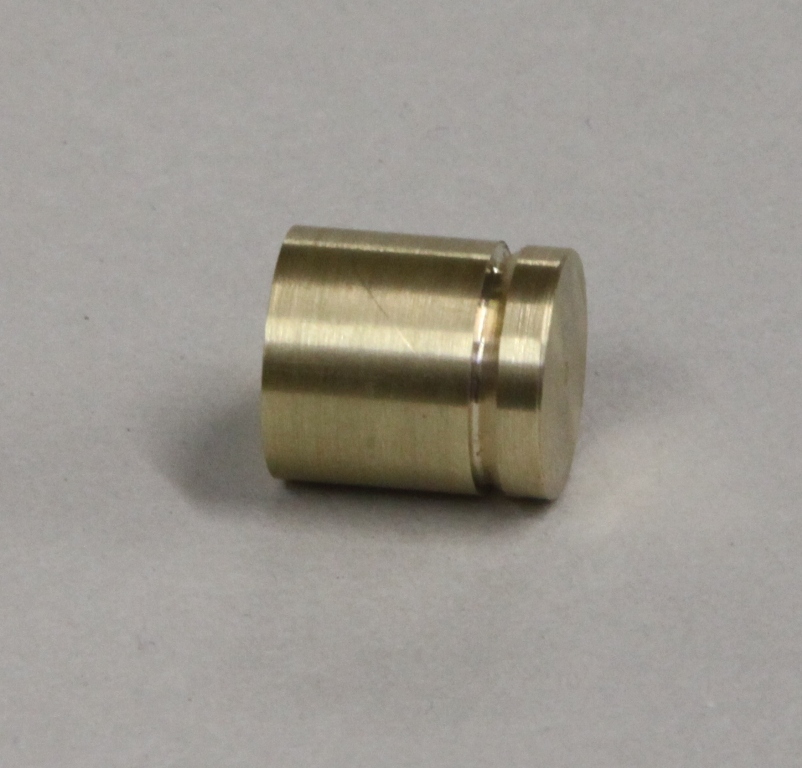
This is the brass insert for the blade bed. It shows a retention groove.
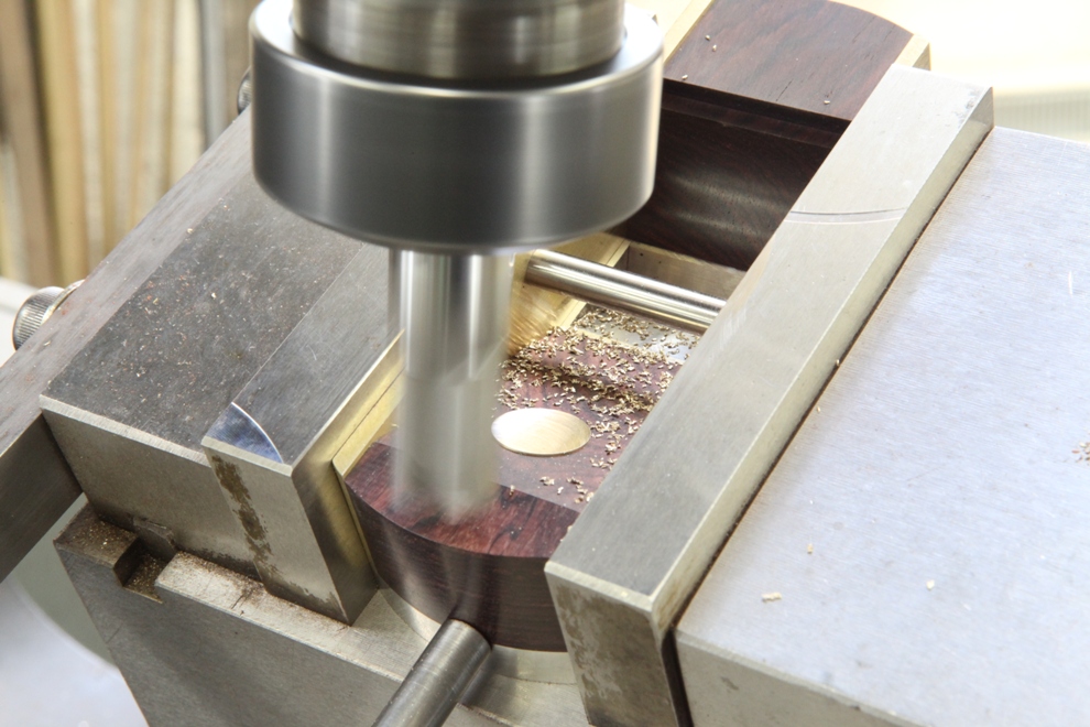
With the plane body set up at the precise bed angle the brass bed insert can be milled to its true height by taking a reference from the frog.
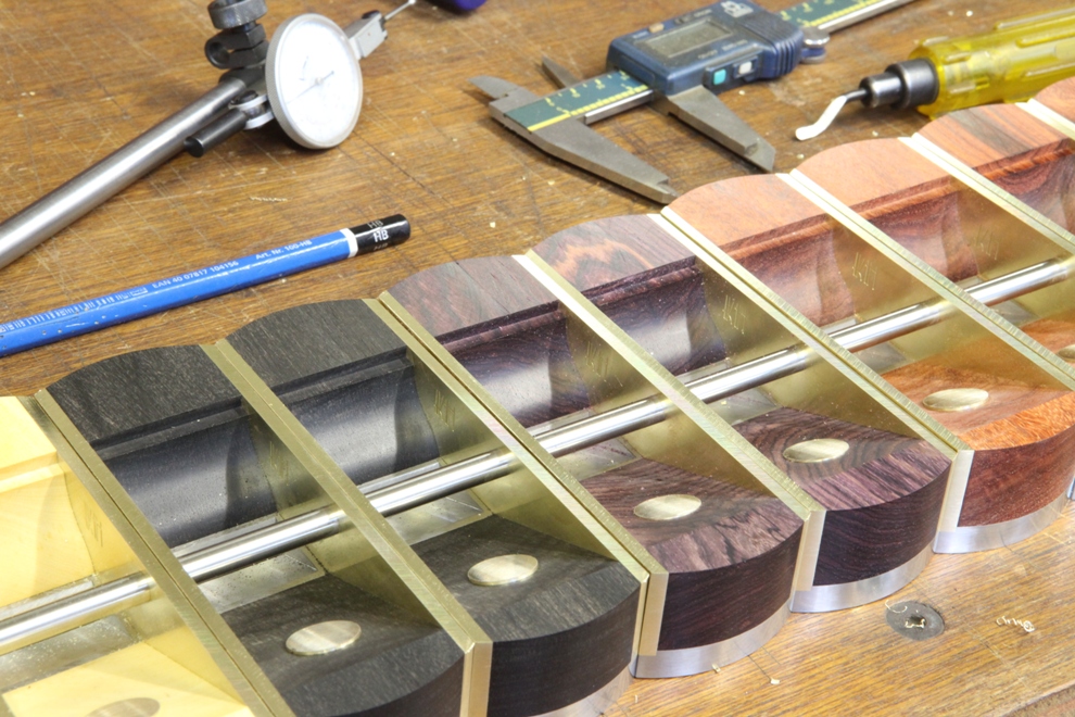
A group picture with a selection of different infills. Sometimes it is nice to see how far you have come.
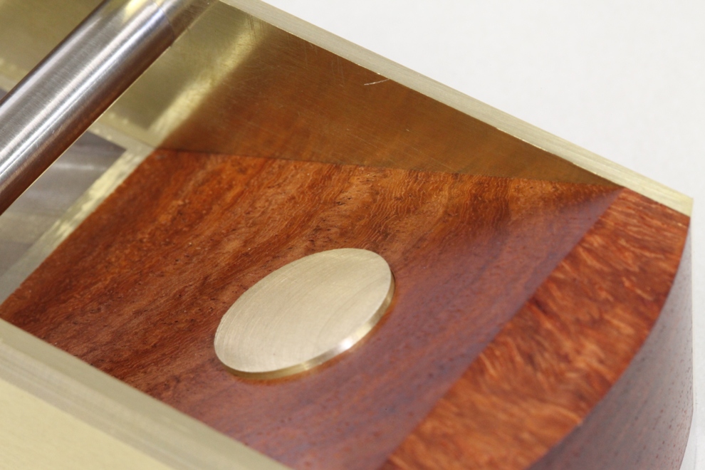
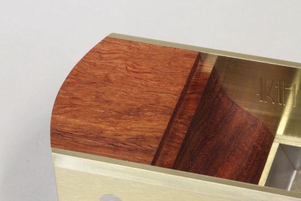
Showing the Zitan infill.
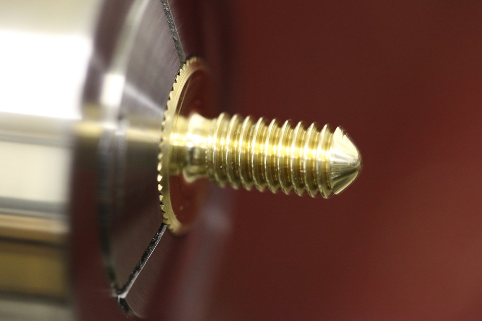
A finished lever cap screw
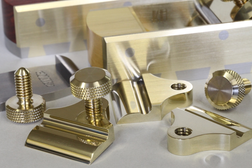
pictures of lever caps and thumb screws finished
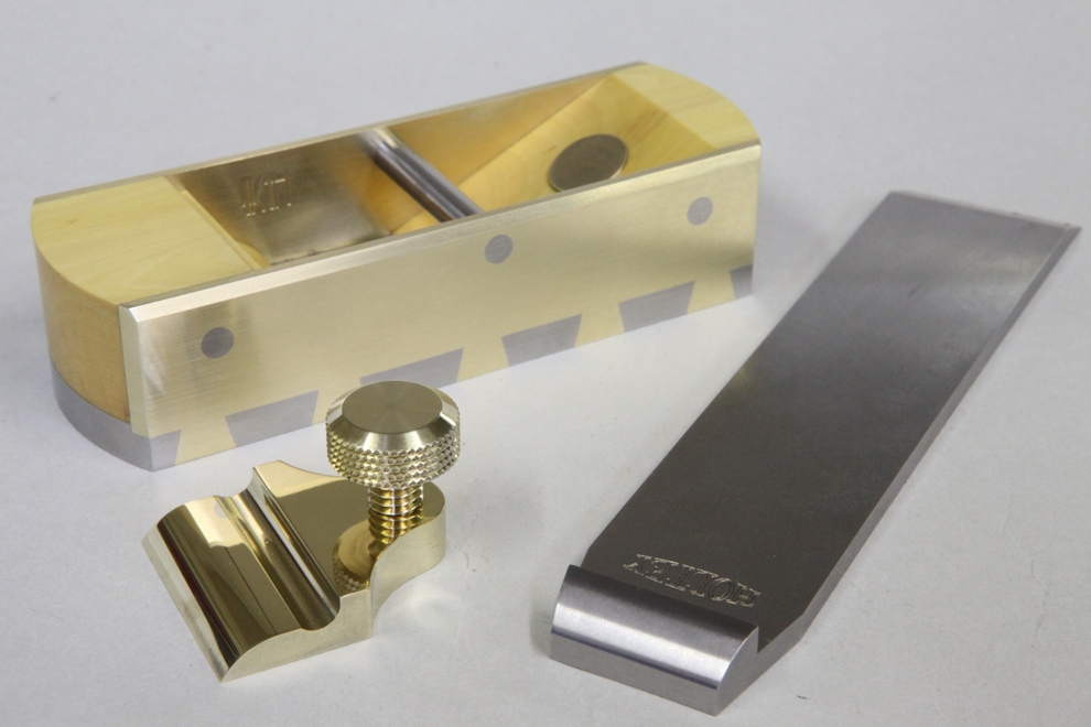
Boxwood infill plane – some people kill for this.
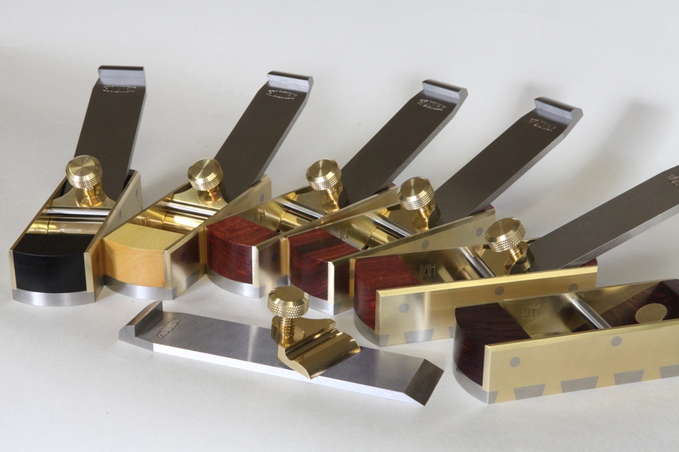
This is the objective.
Objective Achieved !!!
The bevel through the dovetail and the recieving rebate does appear to be Genius ! But hypethetically speaking what actually stops the front part from slipping down the back part ?
i.e. as you pein the two components why is the force of the blow not casuing one component to slip down the other.
Go Karl tell me ?
Best wishes,
Archie.
Comment by Archie — March 7, 2012 @ 7:03 pm
I got so excited I forgot to ask my other question.
Why is the HOLTEY mark that was always so classily and descretely positioned within the mouth of your planes now replaced in this instance with KH ?
I have always admired the sublety of the Holtey stamp and its sneeky little position. Is there are little secret hidden within this new KH that I keep seeing ?
Archie.
Comment by Archie — March 7, 2012 @ 7:36 pm
Hi Archie
I thought I had everything covered, but I don’t understand your question.
k
Comment by admin — March 8, 2012 @ 5:22 pm
Hi Archie
This is the same mark as I used on the No 982 lever cap. The reason I put it on this plane is there is no room for the other one!
Whilst on the subject I think Thomas Norris actually marked some of his planes TN. At least my KH looks nice in its Art Deco styling, you will see a lot more of it in the future.
k
Comment by admin — March 8, 2012 @ 5:23 pm
Hi Karl,
I will attempt to explain my query.
The toe of the plane has a bevel where it meets the rear sole of the plane. This bevel is the joint which is as you quite rightly point out is normally done using a tongue and groove style.
My question is that when you slide the 2 pieces upto each other they meet nicely. then on go the sides and you would turn the plane over to pein the sides and sole. what prevents the toe piece sliding up that clever little bevel joint whilst you are peining the shell ?
Archie.
Comment by Archie — March 8, 2012 @ 7:42 pm
the sides
Comment by admin — March 8, 2012 @ 10:37 pm